Time to start a thread on the next new command 
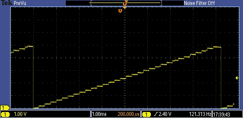
Manual 2 says that the DAC output must be buffered for reliable use (and shows a voltage follower opamp circuit that's bound to prompt a few questions - what's the cap for, what value is it, what's an op-amp, what op-amp should I use, why isn't my op-amp output going right up to 5v etc etc).
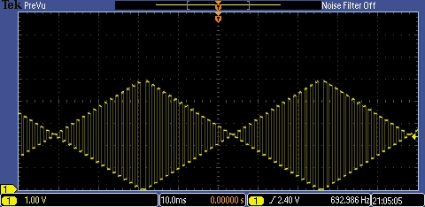
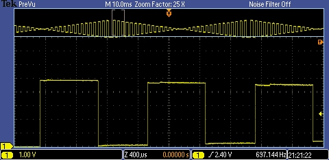
So if I'm using DAC as an inter-PICAXE signalling system (32 levels down one wire to the other PICAXE's ADC pin and a READADC10 in that PICAXE - I wouldn't call it a comms link, but I see the simplicity attractive for simple signalling) is buffering needed?
I suspect not, but guidance would be good.
Hippy - like the task examples you put in the other thread, got any killer apps where DAC will make life easy?
Manual 2 says that the DAC output must be buffered for reliable use (and shows a voltage follower opamp circuit that's bound to prompt a few questions - what's the cap for, what value is it, what's an op-amp, what op-amp should I use, why isn't my op-amp output going right up to 5v etc etc).
So if I'm using DAC as an inter-PICAXE signalling system (32 levels down one wire to the other PICAXE's ADC pin and a READADC10 in that PICAXE - I wouldn't call it a comms link, but I see the simplicity attractive for simple signalling) is buffering needed?
I suspect not, but guidance would be good.
Hippy - like the task examples you put in the other thread, got any killer apps where DAC will make life easy?