Cool PC mod

craig008

New Member
Hi there i am trying to make a cool mod for my PC. basically it will fade LEDs on the inside of the case and light 8 LEDs as a bar, the speed of the fading should be controlled by the temp of the case while also dispaying the temp on an LCD, any ideas on te best way of doing this would be great. I will be using the PSu to supply power.

CODE:
main:
let b0 = 0
let b1 = 0
let b2 = 0

up_1:
let b2 = 0
pause 500 'will be temp reading

up:
let b1 = b1 + 1
pwmout 1 , 99, b0 'PWM up for internal LEDs

let b0 = b0 + 1
if b0 = 255 then goto down_1
if b1 = 32 then LED

goto up

LED: 'LED bar increase
sertxd(#b0,44,#b1,44,#b2,44,13,10) 'connect to LCD
let b1 = 0
let b2 = b2 + 1

let pins = %10000000
if b2 = 1 then up
let pins = %11000000
if b2 = 2 then up
let pins = %11100000
if b2 = 3 then up
let pins = %11110000
if b2 = 4 then up
let pins = %11111000
if b2 = 5 then up
let pins = %11111100
if b2 = 6 then up
let pins = %11111110
if b2 = 7 then up
let pins = %11111111
goto up

down_1:
let b2 = 0
let b1 = 0
pause 500 'will be temp reading

down:
let b1 = b1 + 1
pwmout 1 , 99, b0 'PWM down for internal LEDs

let b0 = b0 - 1
if b0 = 10 then goto up_1
if b1 = 32 then LED1

goto down

LED1: 'LED bar decrease
sertxd(#b0,44,#b1,44,#b2,44,13,10) 'connect to LCD
let b1 = 0
let b2 = b2 + 1

let pins = %00000000
if b2 = 7 then down
let pins = %10000000
if b2 = 6 then down
let pins = %11000000
if b2 = 5 then down
let pins = %11100000
if b2 = 4 then down
let pins = %11111000
if b2 = 3 then down
let pins = %11111100
if b2 = 2 then down
let pins = %11111110
if b2 = 1 then down
let pins = %11111111
goto down

Another question is how many LEDs can i connect to PWM before i need to connect extra hardware, many thanks
________
Plymouth expresso
 
Last edited:

Michael 2727

Senior Member
What Temp sensor do you intend to use ?
I think you need to do a little work to PWMOUT maths.
e.g. PWMOUT 1, 99, b0, the (99) is for 10,000 Hz
and your normal temperature range should only be 25 to 65 DEG C-
so " b0 " will only be 25 to 65 or there abouts.

PWMOUT 1, 99, 25 will only give you 6% Duty @ 10KHz.
PWMOUT 1, 99, 40 will only give you 10% Duty @ 10KHz.
PWMOUT 1, 99, 52 will only give you 13% Duty @ 10KHz.
PWMOUT 1, 99, 65 will only give you 16% Duty @ 10KHz.

PWMOUT RANGE for "99" value = 10KHZ.
PWMOUT 1, 99, 0 will give you 0% Duty @ 10KHz.
PWMOUT 1, 99, 400 will give you 100% Duty @ 10KHz.

A frequency of 40,000 HZ will track the "b" value exactly
in Duty%, e.g. b=10 is 10% duty, b=65 is 65% duty, etc.
USE-
PWMOUT 1, 25, b0

Another question is how many LEDs can i connect to PWM before i need to connect extra hardware, many thanks
A: 20mA worth,
10 LEDS @ 2mA = 20mA (@5V = 1,800 Ohm resistor to each LED )
5 LEDS @ 4mA = 20mA (@5V = 870 Ohm resistor to each LED )
2 LEDS @ 10mA = 20mA (@5V = 330 Ohm resistor to each LED )
1 LEDS @ 20mA = 20mA (@5V = 180 Ohm resistor to each LED )
If you use a 2N700 MOSFET you can drive up to 200mA.
If you use an IRF540 or IRF9540 MOSFET you can drive up to 16A.
( IRF540 hi side switching or IRF9540 low side switching )
And you will need current limiting resistors (20mA) on every LED.

Edit : I may have misunderstood the function.
Anyway the values you are using will still only give
you a Max Duty of 65%.
Try PWMOUT 1, 63, b0. This is 15,700Hz and should track
the byte value a little better.
 
Last edited:

craig008

New Member
thanx for that stuff on the PWM, which the speed will hopefully be controlled be the temp come the end. As for the LEDs, I was hoping to use super bright LEDs in a parralel string to give uniformity to the lighting so i will most likley need IRF540, due to there high pwoer drain.

does anybody now or think i will need some sort of reculator for current as my PSU says that the +5vdc is 38 amps, a bit much i think, unless that is just the mas quoted amount??
________
PORTABLE VAPORIZER REVIEWS
 
Last edited:

Dippy

Moderator
How about a fuse?

I suggest you post a schematic of your proposed circuit as I don't quite understand your proposed layout. I thought I understood it based on your snippet, but "super bright LEDs in a parralel string" and "..need IRF540" has confused me.

Why such a biggun as an IRF540? I thought you were just switching a few bright LEDs?

A drawing would be great to clarify. And also indicate your level of electronics so that people can help more clearly.
 

Michael 2727

Senior Member
How many LEDs, what type and what colour ?
Then we can get an idea of the current you will need.
And what Config, Parallel or Series ?
And as Dippy said, you must include a suitable fuse
or run the risk of destroying your PC if things go wrong.
 

craig008

New Member
thanks for the advice so far guys its been a great help. as for my electronics knowledge, well it is kinda basic as did systems control at school which dealt with design aspects more than what goes into it but programming was one of those aspects.

i was gonna include a fuse any way i was just worried that i would go through alot of fuses if it was going to try and pump 38A through the circuit.

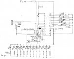
in the circuit diagram i have included 8 LEDs but it will be more than this, most likley in exsess of 12. due to the fact they are super/ulta bright they will be in excess of 30mA each. the other 8 LEDs are standard 5mm ones.

if i have left any components out/made any mistakes in the diagram please excuse me as it has been a while.

oh and was hoping to be able to control the speed of things depending on the temp so ihope this will not put it up too much and this is alot harder than i forst though
________
TORQUEFLITE
 

Attachments

Last edited:

Dippy

Moderator
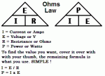
How much current is 'pumped' through your circuit depends on your circuit NOT the 5V power supply. You could use a million amp 5V power supply and still take just a few milliamps. Suggest you have a little read-up on electrics and ohms law and stuff like that.

The fuse is to protect just in case of accidents, component failure, miscalculations and "Oh Dear" scenarios.

Your circuit. I've only looked at LED bits.
1. You MUST have resistors in series with LEDs - assuming they are standard LEDs. LEDs are NOT lightbulbs. You must get the Data Sheet to see current specs. For that number of LEDs you will have to keep the current down or you will exceed PIC specs.
Typically:
25mA per pin with a max of 100mA per port with a max of 200mA total for the PIC ic.
If you wish to exceed those currents you will have to use transistor switching.

2. That bunch of parallel LEDs should be switched using a transistor and ideally each LED should have a resistor e.g. neatest to use a DIL resistor network which look like an ic. You can use a transistor as a low-sided or high-sided switch. 15mA per LED will be pretty bright if using quality High Brightness type, but it varies with manufacturer. Get some Data Sheets.
Even a cheap BC184L configured as a low-sided switch could switch that bunch at 15mA per LED.

What value Resistors? Read up on Ohm's Law and Vf values for LEDs. I = (Vs - Vfled) / R. Rearrange to suit. If using little Rs on prolonged high loads you should also calc power dissipation so they don't overheat.

Get though a lot of fuses? I would have thought it would be sensible to bench test this using a bench power supply before fitting into your PC??
 
Last edited:

MORA99

Senior Member
The computer will not "pump" 38A trough your circuit, just what you draw.
I dont think you need FETs, even with 10 leds on one output line its just 300mA, that can be handled with a regular npn transistor.

You can control flash rates and such using high/low in a loop, but the ones you connect to a shared line will ofcause flash in same speed.

Also you may need a 08m to handle the ds18b20 and maybe lcd, so the main chip dont have to wait for converting the temperature reading, you will then have to find a reliable way to read the temperature from the 08M.

Maybe something like this, then the main chip pulls a line high to request the data to be sent

do
readtemp
wait for line high
send result
loop
 

craig008

New Member
thanks for ur helps guys, dippy ithought that about the power supply but my computer geek friend insistded that it would so i thought i better got some clarification, as for the resistors, thats what i was missing! i was suposed to be working :) must have missed them.

mora99 i was going to avoid using 2 chips, i do however see where you are coming from, i think the final thing may look like this or at least similar

readtemp 0,b0
let b1 = b0 - 70

then use b1 on as my tempo bit (i dunno)

this will cause an over flow alowing it to be slow during norml temp ranges and faster when it gets warm, well at least i hope so - still a work in progress
________
Buy vaporgenie
 
Last edited:

Michael 2727

Senior Member
You could actually do the whole thing with an 08M.
I don't have any 28Xs, and don't think Santa Stocks
them :p but I do have 30 x LM3914 Bar Graph Bar/Dot chips :)
You would still need transistors for the switching.

There are probably dozens of ways you could
do what you want, depends how creative you are.

And your PC Supply is capable of delivering 38A
You don't have to use all of it, you could draw
only 1 microamp and have 37.999,999A in reserve.
( a little basic electronics can go a long way,
buy some books even if they are simple ones )
 

craig008

New Member
thanks for that micheal, it was my friend throwing me all out of wack, and not having done much of this for a year or so, and i do not think an 08M will have quite enough outputs as there are eight LEDs which have a pin each.

if you would like to share some of ur 08m ideas that would be great, i like to see how other people think and find ways around task/problems. not only that the project has only just been started so i cna alwys look in a new direction if it is going to make the job easier and simpler

these are LEDs i will most likely be using, from maplin
http://www.maplin.co.uk/Module.aspx?TabID=1&ModuleNo=45937&doy=5m10

Agilight
Absolute maximum ratings: Ta = 25??C
Power dissipation: 130mW
Peak forward current: 100mA
Continuous forward current: 50mA
Derating factor: 0.4mA/??C
Reverse voltage: 5V
Operating temperature: -25 to +85??C
Storage temperature: -35 to +100??C
Soldering temperature: 260??C / 5secs
________
Vaporizer help
 
Last edited:

craig008

New Member
er may have found a prob, may be me just getting a little pnicy but just been looking data sheets and found most bright super/ultra bright and any others with a clear lense dont seem to take more thant about 3.6v, fine for direct drive but may be a problem when driven through a transistor.
________
Arizona medical marijuana dispensary
 
Last edited:

Michael 2727

Senior Member
NOTE : LEDs have a finite life span, albeit 100,000 hours or so.
The peak rating (100mA) is only for a short pulse, or it explodes, e.g. few mSec.
If you run LEDs at the MAX (I/f )Forward Current (50mA) they can degrade
over a year or less, and keep doing so.
An LED rated @ I/f 50mA will look almost as bright if only driven at 40mA and
will remain that way for much longer than if driven hard.

The LM3914 is a Bar Graph driver ( Stereo LED volume indicator, 8 LEDs, etc )
You could drive the LM3914 input from an 08M PWMOUT with a R/C network,
Resistor/Capacitor, to smooth/average the output.
"Search, here" should turn up several previous topics.
 

craig008

New Member
that sounds good, but i have another question for you what LEDs should i use, this is gonna be an issues i think as the fading LEDs will be driven through a transistor which means the voltage will be at 5v and not close to 2.5v, and what soze capicitor and resistor would you recomend,
________
Toyota tf107 specifications
 
Last edited:

craig008

New Member
at the mo we have a 5.5v supply unless there is something i missed back along, or i am getting confused again (not too hard is it). see my thinking was that is might step the out put voltage of 2.3v or so at pin up to what ever but judging by ur comment this is not true. u know i did not realise how much of this stuff i had forgotten - not that we did much with transistors in schol anyway.
________
Rv90
 
Last edited:

Dippy

Moderator
Grapes.
First, I think you should make your mind up as to which PICAXE you are going to use and then the method. It looks like you are confusing the methods as I can't see where 2.3V comes from.

IF you are going to use the 28X plus your code, then your fading can be done as said by Michael using PWM. But I'm not sure if your fading is for the 8 parallel LEDs or for all of them?

Anyway, that needs clarifying as it changes the circuit requirements.
The PWM output is nominally 0 to Vsupply where you can adjust the frequency and the duty (the ratio of ON:OFF). A 50% duty on a 'scope can be seen as a square wave alternating between nominally 0 and +Vsupply.

If we can clear this bit up first then we can get onto the transistor switching....
 

craig008

New Member
i will be using 28X seeing as i have one spare, its seems that it has been a long time and that i am getting lots of circuits mixed up, kinda glad i came here before i got too far through this project. so you all know this is the most complex project i have undertaken - this is one of the reasons i like to see how other people go about similar problems/projects
________
Mazda az-wagon history
 
Last edited:

Michael 2727

Senior Member
All LEDs have a Forward Voltage drop, like a normal Doide.
This is the voltage they start to turn on at.
A standard RED LED may be 1.5V
A standard GREEN LED may be 1.7V
A standard Blue, White or UV LED may be 3.6V

In general terms you can drive an LED from almost
any voltage, even 100 volts or more,
BUT ONLY IF THE CURRENT IS LIMITED TO
WITHIN THE SPECS OF THE LED USED, e.g. 20mA


How you work this current out is -
The Voltage used, minus the LED V-Drop, divided by
the resistor value that allows the correct amount
of current to flow. Use Ohms LAW, it's not hard


e.g. RED LED = 1.5V, Voltage used 5.0V
5.0V minus 1.5V = 3.5V divided by 220 Ohms
= 15.9 mA of current will flow. LED survives.

e.g. RED LED = 1.5V, Voltage used 93V
93V minus 1.5V = 91.5V divided by 4,700 Ohms
= 19.4 mA of current will flow. LED survives.

e.g. RED LED = 1.5V, Voltage used 12.0V
12.0V minus 1.5V = 10.5V divided by 220 Ohms
= 47.7 mA of current will flow. Your LED is dead.

There are thousands of pages on the web where
you can find electronics info and calculators,
Go get some, they're free.
Plucked at random -
http://www.arfunk.com/amrad/passexams.html
http://led.linear1.org/1led.wiz
 

Attachments

Last edited:

craig008

New Member
so if i am using 5V adn my LED foward V is 2.3v
5v - 2.3v = 2.7
2.7V / 0.020A = 135 ohms
so a 150 ohm resistor wil do nicely and keep the LED within its operatonal peraminters
2.7V / 150ohms = 0.018A or 18mA
________
Honda VF and VFR specifications
 
Last edited:

Dippy

Moderator
One step further with Transistor switching:
The total 'V' term in the I=V/R equation is

(Vsupply-Vfled-Vce)

Vsupply for your example is 5V
Vfled is the forward voltage drop of the LED as you have seen
Vce is the transistor Collector/Emitter voltage drop (Assuming you're saturated)

Sadly, Vce varies with load so sometimes a quick test on bread-board is easiest, but an example:
A BC184L will have a Vce of about 0.1V at 50mA. (Well, the one I just tried did anyway!)
So:
I = (5-2.3-0.1) / R

50mA is far too high to run an LED continuously, it is just an example.
Personally, for good High Bright LEds I wouldn't bother over 15mA if you intend to stare at them. Depends on LED - have you read Data Sheet and compared different manuf's specs? No? Brightness @XmA can vary hugely between manufs. Check Farnell's website, they have a huger range than Maplin.

Back to the plot: As you reduce your R term and increase I/current you will find that Vce increases. A slight dimishing return - particularly important btw when pulsing IR LEDs at high power.

Slightly different if using a MOSFET of course , so I'll leave that one with you.
 

craig008

New Member
so i am just gonna check i ot this right for a mo here;
i will have my fading super bright LEDs conected in series with resistors not running more than 15mA, the + of LEDs will connect to +5V and LEDs/resistord will connect the transistor collector, and Emitter from trinsistor will go to ground while the base will connect to the picaxe through a resitor and capacitor (capicitor to ground transistor connects and resistor and capicitor junction). then ontop of all this i need to ad in the transitor forward current which i ques means i may need to drop the LED resistor values, i wil look into this a bit more, thanks for the info Dippy

so if the transisor has a Vce of 0.3V
LED Vfled of 2.3V
supply 5V
5 - 2.3 - 0.3 = 2.4
2.6 / 150 = 0.016A of 16mA

one further question, what factors should i take into account for have alot of LEDs, or will this make no difference, oh and what are your recomendations on resistor and capicitor for the PWMOUT
________
MARIJUANA STRAIN INDEX
 
Last edited:

Dippy

Moderator
I wouldn't bother with a capacitor (assuming I understand you correctly).

Lot's of LEDs.
Assuming your're talking about your parallel LEDs (each with a res) then you're only worry is whether the TOTAL current overcooks the transistor you choose.

And I still don't know whether you wish to fade(using PWM) all of the LEDs (i.e. the 'bar' AND the 8 LEDs in parallel).
If you wish to fade your LED bargraph you will need to include another tansistor whose base/gate is controlled by the PWM out. Value of resistor? Well that depends on your type of transistor you wish to use. If I were doing it I'd use a ZVN2106A, but that's only 'cos I have a drawer full.
If you use your circuit for the bargraph with each LED at 15mA you will exceed the port current limit for the PICAXE. This may be a job for old faithfull ULN2803 or similar with low val res on each LED - I haven't checked. Or, alternatively, limit the bargraph LEDs to 10mA each. I'm sure some high bright LEDs will be plenty bright if you are looking at them (as opposed to using them to illuminate - again I don't know your setup).

Note: You should have a decoupling cap connected close to PICAXE V+ and V- pins as all that PWMing may introduce noise. And your PC power supply will produce noise too.

I'm sure some kind soul can draw a modified circuit diagram for you. There are a number of options here depending on your requirement and budget and component availability depending on your Country.
 

craig008

New Member
i will draw up another circuit diagram later for you wich should hopefully be it, will a 100uf cap be enough between +v and ground, so you know i will not be using the bar graph circuit

this is waht i ahve for the programme so far

main:
let b0 = 0
let b1 = 0
let b2 = 0

up_1:
let b2 = 0
readtemp12 0,w5
w6 = w5*10/16
b4 = w6/10
b5 = w6/16 'will be temp reading

up:
let b1 = b1 + 1
pwmout 1 , 63,b0 'PWM up for internal LEDs

let b0 = b0 + 1
if b0 = 255 then goto down_1
if b1 = 32 then LED
let b6 = 65 - b4
pause b6
goto up

LED: 'LED bar increase
sertxd(#b0,44,#b1,44,#b2,44,13,10,"Temp: ",#b4,".",#b5,13,10) 'connect to LCD
let b1 = 0
let b2 = b2 + 1

let pins = %10000000
if b2 = 1 then up
let pins = %11000000
if b2 = 2 then up
let pins = %11100000
if b2 = 3 then up
let pins = %11110000
if b2 = 4 then up
let pins = %11111000
if b2 = 5 then up
let pins = %11111100
if b2 = 6 then up
let pins = %11111110
if b2 = 7 then up
let pins = %11111111
goto up

down_1:
let b2 = 0
let b1 = 0
readtemp12 0,w5
w6 = w5*10/16
b4 = w6/10
b5 = w6/16 'will be temp reading

down:
let b1 = b1 + 1
pwmout 1 , 63, b0 'PWM down for internal LEDs

let b0 = b0 - 1
if b0 = 10 then goto up_1
if b1 = 32 then LED1
let b6 = 65 - b4
pause b6

goto down

LED1: 'LED bar decrease
sertxd(#b0,44,#b1,44,#b2,44,13,10,"Temp: ",#b4,".",#b5,13,10) 'connect to LCD
let b1 = 0
let b2 = b2 + 1

let pins = %00000000
if b2 = 8 then down
let pins = %10000000
if b2 = 7 then down
let pins = %11000000
if b2 = 6 then down
let pins = %11100000
if b2 = 5 then down
let pins = %11110000
if b2 = 4 then down
let pins = %11111000
if b2 = 3 then down
let pins = %11111100
if b2 = 2 then down
let pins = %11111110
if b2 = 1 then down
let pins = %11111111
goto down
________
Vapir no2
 
Last edited:
I will have a go making a new circuit diagram, it should be done about 6 hrs from now.... Sorry if it is rough/incorrect.
 
Last edited:
You may want to edit up_1 and down_1 to

%TOP HALF (variables)%
readtemp12 0,w5
w5 = w5*10/16
b4 = w5/10
b5 = w5//10

as that reduces variable usage and the tenths are actually displaying tenths...
 
Last edited:
I have uploaded a modified circuit diagram, as dippy requested here.

I will update schematic as project moves on.

In this example you can make them fade or not, just choose the transistor to suit. All led's have a 150 Ohm resistor which should be ok. The ULN2803 is simply a set of 8 transistors, whose bases(?) is connected together, in a IC box, and only costs 65 cents(less than 1/2 the price of an LED...)on ebay.

Now I look at them.....
I might buy some of those ULN2803's for myself - thanks dippy for pointing these out!
 

Dippy

Moderator
Xnerderlandx: Your circuit is wrong.
The ULN2803 is a sink not a source - I know it sounds silly to say 'out' on the Data Sheet but please check it out. Each LED should run +V -- Res ---- LED --- ULN2803'Out'.

You have no resistor going to PNP base.

"The ULN2803 is simply a set of 8 transistors, whose bases(?) is connected together..".
Nah. It's 8 Darlingtons with common emitters. It's written on line 1 of the ST Data Sheet if you read it.

Slight Aside: The use of Darlingtons + LEDs at lower supply voltages is something which you have to consider because of the higher Vce compared to simple Bipolars. Just a note when calculating things.

The 100pF cap on PICAXE should more like 100nF. I'd like to see a >100uF cap on the collector side of PNP too. You may need more if the PC supply is noisy. You'll only find this out when you try it.

Grapes: "..so you know i will not be using the bar graph circuit."
Your code suggests you are using the bar graph - I'm confused.

I think I'll leave you in Xnerderlandx's capable hands now as I'm puffed out.
 

craig008

New Member
thanks guys for ur help, and dippy i know what u mean and thought you ment the pwm bar graph that was suggested earlier. as for the capacitors the one for the trasistor should be the same set up as the one for picaxe from +v to base with 4k7, resistor from chip to transistor.

xnederlandx what software did u use for the diagram, where can i get a copy of it, thanks for the diagram its better than my hand drawn one
________
Vaporizer reviews
 
Last edited:
I used Power Point then Print-screened it on all four parts, and stuck it together with paint, then optimized it using paint.net. I will upload the .ppt into folder after I have fixed it up...
 
Last edited:

craig008

New Member
cool, sounds simple. just been doing some research on transistors on the web site for my local electronics store, but they do not give much info about them other than high frquency or low, what should i be looking at
________
HONDA GL1200SEI
 
Last edited:

boriz

Senior Member
In general, for most hobby stuff, the factors you should use when choosing a BJT transistor (in order of importance) are:

1. Polarity – NPN or PNP.
2. Ic(max) - The maximum collector current.
3. Hfe(min) – The minimum gain.
4. Vce(sat) – The voltage drop across the collector-emitter junction when the transistor is fully ‘on’ (saturated).

Polarity:
Referring to your diagram. You are using a NPN transistor as an emitter follower (the voltage on the emitter follows or tracks the voltage on the base, less of course the 0.7v diode drop between base and emitter)

Collector current:
Assuming an LED forward voltage of 1.7v, the sum of currents through the collector is about 250mA. So you need a minimum Ic(max) of 250mA. But you will find that you always need a large overhead when judging these figures, so an Ic(max) of at least 1A would be more suitable.

Gain:
Since the base current is supplied by the PICAXE, and therefore limited to around 20mA max, you need a gain of at least 12.5 (250/20 mA). BUT!!!

FIRSTLY, for reliability, you should not load the PICAXE at it’s maximum and there is no need to.

SECONDLY, the gain figures quoted for transistors are for collector currents that are only a small fraction of Ic(max). For example I have a NPN of around 520 Hfe and 100mA Ic(max), but that 520 figure is measured with an Ic of only 2mA!. The gain drops rapidly as Ic increases. By the time the collector current is about half Ic(max) the gain will have dropped to maybe less than 50. Misleading isn’t it :)

THIRDLY, again, always have a large overhead where possible. Go for an Hfe of at least twice what you need, at the intended Ic.

For a follower, the Vce(sat) is not very important. It usually only needs considering when efficiency is a major factor.

So. For this application I would recommend a transistor with the following MINIMUM specs: NPN, 1A Ic(max), 30 Hfe @ 250mA Ic. If you start shopping around, you will find hundreds of transistors that will fit the bill. 250/30=8.3 so the PICAXE will be comfortable supplying 8.3mA.

I personally always stock 3 types of NPN transistors (and their PNP equivalents): BC549 for low current high gain signal stuff (Hfe 520 @ 2mA, 100mA IcMAX). BC639 for medium power stuff (Hfe 40 @ 150mA, 1A IcMAX). TIP31a for high power stuff (Hfe 25 @ 1A, 5A IcMAX)

From my own stock, I would choose the BC639.

EDIT:
BTW. Since you are using the transistor as a follower, you do not need the base resistor. And I would remove the 100uF capacitor from the base to +5v also.
 
Last edited:
The new schematic has been uploaded, it is called Latest Schematic.gif and is about 54Kb

Grape: PowerPoint is there too, it is called schematic.ppt

Another link for your convenience: Click here
 
Last edited:

craig008

New Member
wow thanks for all ur help guys, i will start construction later today. just incase you are wondering my forum name game from the bag of grapes i was easting at the time

i will try and get the higher power option just in case i need to add more LEDs, this should allow enough space for as many as i like. i know i can definetly get te BC369 so that is an option

just fond this too, i can get the TIP31c which looks as tho it will do the job too
http://www.onsemi.com/pub/Collateral/TIP31A-D.PDF
________
Vapir No2 Vaporizer
 
Last edited:
Top