Constant wattage load for discharging a battery

Haku

Senior Member
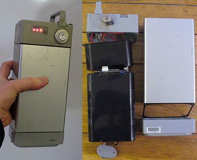
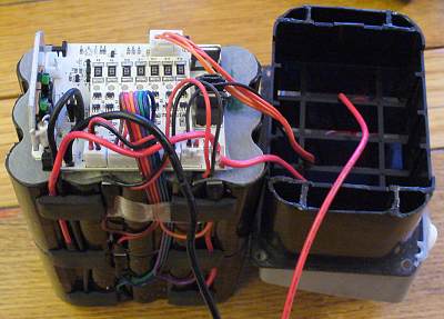
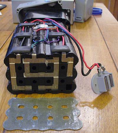
In a few weeks time I'll be ordering a large batch of 18650 sized li-ion cells from China because I intend to re-cell one of my ebike batteries which has 28 of these cells inside, the price of a new ebike battery is £329, but 28x 3800mAH cells starts at about £50 from China.

I'll be ordering more than I eventually need because I don't want to blindly drop in 28 3800mAH li-ion cells into a pack (albeit with a strong aluminium case) without testing them beforehand, and to find out if there are any bad cells in the order and also try to match minor capacitiy differences (the pack is made up of 7 sets of 4 in parallel), I intend to build something to test the capacity of the cells, powered by a Picaxe with LCD screen, control buttons etc.

My main query here is regarding the discharge capacity test of the device, the DIY battery capacity tester here - http://www.instructables.com/id/Arduino-True-Battery-Capacity-Tester-Li-IonNiMH/ - uses a 10 watt 2.2ohm resistor as the load.
Does that mean the resistor will put a 10 watt load onto the cell no matter what the voltage of it is?

The final device will have charging capabilities through use of commercial chargers, and the ability to test more than once cell at the same time because running the test on 28+ cells will take quite a time.

Also, is there anything I should be looking into/be wary of when dealing with charging/discharging li-ion cells? I am aware of the dangers of over/under charging & shortcircuiting them.
 
Last edited:

Goeytex

Senior Member
Does that mean the resistor will put a 10 watt load onto the cell no matter what the voltage of it is?
No, the wattage will not be constant. As voltage drops, current will also drop, therefore wattage will drop.
Ohms Law.
 

SAborn

Senior Member
Would logging 3 cells at a time be good enough for what you want to do?

The reason i ask, is some time back i helped a person with a school science project who wanted to record the discharge curve of several different batteries (carbon, alkaline, etc) for this i introduced him to using a picaxe and the data was logged to a computer so the graphs for the discharge curve could be displayed in relation to discharge time.

A friend wrote a small VB program to record and display the data, all the picaxe do is read the adc and send the raw data to the PC, all calibration is done in the PC, this is the same style we use for logging data from wind turbines.

If you would like i could share the VB software with you if it would suit your needs.

To me this would be a far superior way to monitor the data compared to just a lcd display.

It is limited to 3 cells at a time.

Pete.

Battery Cell Logger 4.JPG
 

Dippy

Moderator
A brief look at the "fantastic circuit" (?:)) gives me no 100% answer. It suggests a simple load design with a resistor and feedback.
For a general purpose circuit I would say it is lacking in thought and definitely lacking in MOSFET experience. A LED in series with gate is a bit 'schoolkiddy' and could give unwanted behaviour.
I would suggest you design a better one.
It's a piece of cake.

I suspect the MOSFET is merely switching the discharge resistor bit.
Experience of other discharge tests are simple resistor discharge.
Therefore Ohms Law - therefore NOT constant wattage.
As you will be comparing your battery performance like-for-like (back-to-back , A-to-B) then I have to ask "Why bother trying to make it overcomplicated?".
I think a CC circuit woult be OTT , but up to you.

Don't forget to calculate the resistor wattage that YOU require , then double it and choose your resistor.

The true answer is to contact the Manufacturers and get their response, I just hope you can speak the lingo.
All tests will be documented if the Company is pukka.
 

srnet

Senior Member
Well you could build your own, but it is normal to monitor capacity by discharging at a constant current, until the minimun voltage is reached.

However for not a lot of money you can get a piece of kit designed for the job;

http://www.giantcod.co.uk/icharger-106bplus-250w-balancecharger-p-404527.html

It will cope with just about all the various battery chemistries, including LiFePo4, which I am guessing is what you are using.

Lots of charge options, does dicharging at a selectable current, will do cycles of charge & discharge and will (via the USB and a bit of free software) generate logs and nice graphs on a PC of discharge, mahr, wattage and other stuff.

The do a 1000W\30A version of the charger too ......

There are cheaper versions you can find on eBay which will do what you want for about £25, maybe less.
 

Haku

Senior Member
@Goeytex, I thought so, there's still alot about electronics I don't know which is why I'm asking questions before doing anything.

@SAborn, thanks for the offer, if things go that direction I'll ask.

@Dippy, some of what you said made a *woosh* sound as it went over my head but I get the jist of things.

@srnet, basically I need some way of doing a charge/discharge/charge test on all the li-ion cells so I can find out their capacities and match them up, once that's done they'll be soldered in parallel in sets of 4, and those resulting 7 sets will be soldered in series. After that I won't need the testing device until I make a new pack, the ebike battery charger will charge the battery pack from then on.


Looking more into the 18650 cells out there I realise I'm going to have to spend probably double my initial estimate because the cells I was looking at are most likely fakes, random repackaged brands with wildly varying capacities, I'll need a batch of identical cells that won't crap out when you put a high load on them - a lithium fire on that scale is something I definitely do not want.
 

Dippy

Moderator
Sorry, didn't mean to chuck in negativity :)

Basically, you will take your identically fully charged batteries and discharge them through a known load whilst logging the V-drop (IR) drop across the load. Then you choose your closest matches to make into a pack. Is that right? Sounds like a good plan.

You could use a good MOSFET or a good relay for the switching.
You could monitor ADC either side of the load to check that the switch (assuming low-side relay or MOSFET) to allow for switch resistance and some thermal issues.
Then you would have all the parameters to produce a pretty decent discharge curve or even just timing from full to flat.
After all, all you want is to compare like-with-like cell at a time.
It doesn't matter if it isn't bang-on 100% scientific as any slight errors in method are cancelled out.

I can't comment on quality of source of batteries; you may get good value or you may get a headache - your risk.
It depends on the equation of risk vs price vs importance.
The vendor may refuse to take returns as (in some fairness) they won't know the qaulity of your charging method even if you find a genuine duffer.
That's a calculation only you can deal with.
 

Haku

Senior Member
Sorry, didn't mean to chuck in negativity :)
No no don't worry about that, it's all new information to me and I'm enjoying still learning all this mystic wizardy people call electronics :)

Basically, you will take your identically fully charged batteries and discharge them through a known load whilst logging the V-drop (IR) drop across the load. Then you choose your closest matches to make into a pack. Is that right? Sounds like a good plan.
Yes that is the intention, to give a number to each battery that represents their capacity so I can pack them in matched sets of 4 and weed out any that fall way below the average, if I can work out the actual capacity in mAH that would be welcome but not important.

Mostly when buying from China my attitude is "oh well it was cheap I shouldn't expect miracles" and usually the item turns out to do exactly what it says on the tin and I'm happy, but on this occasion I don't want any nasty surprises so I've got to tread carefully.


I recently modified one of my two ebike battery chargers using a MOSFET + 08m, the additional circuit disconnects the battery from the charger after it's finished charging through use of the MOSFET so it's not left trickle charging for hours/days on end. It's rather neat, the 08m can detect when a battery is connected and wether it needs charging.
This upgrade should help with the new battery pack I'll be making, another layer of charging protection, and hopefully extending its life.
 
Last edited:

lbenson

Senior Member
... I recently modified one of my two ebike battery chargers using a MOSFET + 08m, the additional circuit disconnects the battery from the charger after it's finished charging through use of the MOSFET so it's not left trickle charging for hours/days on end.
Sounds like a good candidate for the Finished Projects forum.
 

SAborn

Senior Member
Should you do decide to want to log the discharge /charging curves to a PC, then you will get a graph something like this one below.

I would think if all cells were tested using the same load then you would get some clear data to how each cell behaved for easy matching of cells.


Graph shot.JPG
 

John West

Senior Member
I suggest logging one cell at a time in whatever setup you decide to use. That way you can easily compare discharge curves. Matching them is the key to series/parallel battery packs, so using the same test setup for each cell is key.

Also, a high discharge rate is helpful to test the cells in a test most similar to actual operational discharge. I'd suggest a load resistor or constant current discharge circuit be selected that does about a 2.5 A discharge in order to come close to an operational discharge in order to catch any battery anomalies.
Regarding the above post regarding loads, note that each LM317 is rated at only 1.5A and that the minimum operational voltage is 1.2 vlots.
 
Last edited:

Paix

Senior Member
I recently ordered RF-2400P from Inhaos.com in China, with free postage. The possible downside is that it might take 35 days or more before you get your batteries.

My buy was relatively inexpensive so the fact that my confidence was beginning to waver was really not a nail biting experience and they turned up at about 39 days, having done the slow boat bit, although I did notice the package did say Par Avion. Must have been one of those Cathay Pacific Jumbo Jets held up at the traffic lights, just like the TV adverts.

Previous imports from HK have normally dropped onto the mat in under a week, so the experience from mainland China and more particularly I imagine due to the free postage was a new experience. Just in case you are expecting sub one week delivery and depending upon it. The eBay page did give a delivery estimate, but it was beyond my prior experience and I didn't actually note the delivery window cited.

Happy with my purchase though.
 

Haku

Senior Member
@lbenson, I'll get to work on something, I haven't actually got any proper documentation on the wiring diagram, I went straight from breadboard to stripboard :)

@WHITEKNUCKLES, that's an interesting way of discharging a battery, I have a load of LM317T's in my parts collection and some old PC fans with heatsinks. The motor on my ebike is rated at 200 watts so can theoretically draw a steady 26+ amps from the battery, roughly making it 1 amp per cell. Certainly something to look into.

@booski, thanks for the link, the price is very nice but I need tabbed cells as I don't have the necessary equipment to spot weld onto batteries, and would not attempt to do so on lithium cells with a soldering iron.

@John West, I want to get a working circuit and make 3 or 4 identical ones to reduce the overall time involved with testing 28+ batteries, as testing 4 a day it'll take over a week to run all the tests and would be nice to halve that.
 

WHITEKNUCKLES

New Member
Haku, I am having trouble with your numbers.

28 cells as sets of 4 in parallel and 7 sets in series for ~ 26V.
So each cell will carry one quarter of the total current which is unlikely to be 1A as in your last post.

Your 200W motor could draw a "steady" 200w/26V = 7.7A where you expect 26A.

But it is rated at 200W continuous output which could mean a short term output greatly in excess of this. Bike motors are not noted for meltdown and a motor climbing hills for half the time at 400W would still be within the rated output of 200W continuous.

My own 26V Panasonic 250W can draw a measured 14A maximum on steep hills when the pedal torque sensor is set to deliver 1.3 times my input power.
So I think it would be reasonable to assume a max of 15A for yours if the controller permits, giving a current of 3.75A per cell.

My batteries are rather old so I have great interest in your progress.

Dave
 

mrburnette

Senior Member
Well... I love this forum because 'no matter what' the topic, the variety of responses are fantastic. In this battery-case (no pun), there are lots of issues that can be dealt with individually, but we probably need to step-back from the trees and look at the forest for a moment...
The goal is to match cells into a series pack. Then well will parallel those packs... the initial thinking is to provide for the peak/run-time current of the electric motor but actually the motor could be run from just one pack... so what we are trying to accomplish is to minimize the cell-load in each pack to reduce the overall current to 25% that is dropped across the internal resistance of the cells in the pack. This reduced voltage drop as a byproduct of reduced current then produces less I^2R (Watt) loss to heat. With parallel packs of high amperage cells, there is a possibility that one pack output voltage would "buck" another pack if the voltages were not perfectly matched, but the internal resistance in the cells actually prevents this from happening so the terminal voltage is constant but the current in each series pack may be slightly different throughout the discharge cycle - with Solar Cells, Shockley diodes between parallel cells prevents this from happening.
So, to put theory into motion, I personally would attempt to match packs first... that is, assemble the series strings, put them into the bike, and free-wheel the system for a few minutes while recording the output voltage and monitoring the temperature of the individual cells... a perfectly matched set of batteries in series will produce a perfectly match range of temperatures... use one of those inexpensive IR digital thermometers to measure. If you find one cell getting hotter, replace that cell, recharge all batteries, and rerun the load test. Assemble another string of batteries, retest, and match. Assuming that you never deplete the assembled pack by more that 20%, you should have no great worries.
Since we are on the PICAXE forum, you could use the A-D channels with thermistors to monitor the assembled pack. Assuming that you could slide in a thin sheet of copper to use as a heat-spreader between each of the parallel cells, you could then monitor the entire pack with 4 matched thermistors. Use a thin sheet of high temperature silicon (cut from a kitchen silicon baking sheet) to separate the copper from the next cell pack. Essentially, you will wind up with (L2R) battery case, battery, copper, silicon, battery, copper, silicon, battery, copper, silicon, battery, copper, silicon, case. The silicon conducts heat but also provides a small thermal resistance from the next cell pack... if we have a pack that is overheating then the temperature of the copper spreader will become higher than the adjacent pack (or case.)

- Ray
 

papaof2

Senior Member
I looked online for a constant current load to test some PV panels. If you search for
constant current load
or
constant current discharge
you should find several versions - some much simpler than others.

Don't remember where I found it, but the attached is one of the simpler designs. If you don't need the multiple discharge values, it could be very simple.

John

View attachment discharger.pdf
 

fernando_g

Senior Member
My two yen on the subject, based on experience (both personal and from fellow engineers) with chinese-made components:

Buy at least 10% more batteries than what you really require. Then test and categorize each cell individually. You'll find out that at least 10% of them are crap.
Since the capacity in a series battery string is determined by the weakest cell, a single crappy cell will cause your overall capacity to be crap too.

But even with that 10% surcharge, you are still ahead of the price game.

The discharger circuit proposed by papaof2 is a good, simple circuit. Just make sure your mosfet has ample heatsinking. A small fan would also help.
 

Haku

Senior Member
@WHITEKNUCLES, yeah I'm having trouble with my numbers also, I'm not used to dealing with such high figures regarding number of batteries plus the voltage and ampage involved. One day I'd like to install one of those watts-up meters on one of my ebikes (I have 3) to find out what the actual maximum current draw is.
Whatever the outcome, wether I buy or build a cell testing device, I will certainly post back here because this isn't one of those "one day I'll make that" projects, my 3 battery packs are all years old and give very limited range which I'm struggling with (sometimes I take a 2nd pack with me) so I need a new pack soon because the cold of winter just makes the capacity worse.


@mrburnette, I will be matching cells as closely as possible, which is why I'll need to make or buy something that can test each cell to find out its capacity under a typical load experienced when inside an ebike battery pack.
Unfortunately the idea of testing the cells voltage/temperature after being placed in the battery pack and running the motor for a while will probably prove impossible, the 28 cells in the pack are held in place with 2 special plastic holders that are designed to each hold 15 cells in a 3x5 grid.
The BMS inside the battery packs does monitor the 7 sets of 4-in-parallel cells during charging, and there's 2 thermisters to monitor temperature, presumably when charging and hopefully when running so it will shut down if it gets too hot.
The BMS will shut off the output if the overall voltage drops too low and (I found out by accident) that it also has short circuit protection on the output.


@papaof2, thanks, it may come in useful when I get down to deciding on building or buying a device to test cells.


@fernando_g, I certainly intend to buy more than I eventually need, probably go for 35-40 cells, hopefully enough to get a good set and any leftover will be used for future unknown projects.
I think one or more of the cells in two of my three battery packs has failed because those two don't hold their fully charged voltage (29.4v) very long after charging. All are over 2 years old with one being 4 years.


Still having trouble finding a reasonably priced source of 18650 li-ion cells in bulk from somewhere that at least looks trustworthy so what's printed on the battery is what's in the battery. Back to Google, ho hum.
 

srnet

Senior Member
I parallel 2300mAhr Lipo packs in one of my planes, apart from using the same type of pack, no special matching is needed.

The motor can draw up to 40A, which one of the batteries can supply on its own, I parallel them for extra duration.

When your using the batteries at very high currents its fairly important to balance charge the packs. Lipos for RC model use have a balance tap which allows the battery to be balance charged so that the individual cells are closely matched charge wise.
 

Dippy

Moderator
Why has this battery dicharging test become so complicated?
You flatten them in a controlled and sensible way, you monitor it, you time it.
What's wrong with an appropriate resistor?
Why go to all this constant current discharge?
It is simply comparative. Easy.
And I think Haku has had 20 replies telling him/her to match the batteries .... I think he knows :)


Haku, if you spend much longer searching for batteries you may has well have bought them from a proper retailer and just bought one extra spare.;)
Is there that much difference in price?
And then you'll have half a tonne of Chinese lithium to store safely in your bedroom.
Never mind, their growth has dropped from 9.8% to 9.1% so I feel it is your duty to help get it back up :rolleyes:
 

Haku

Senior Member
Here's a couple of pics of the battery pack in question:


@Dippy, I don't have the money to buy the cells for a couple of weeks which gives me plenty of time to search for a cell source and to read up on lithium batteries (18650 variants in particular) as my only previous hands-on experience of using them are the coin type for watches etc. and the rechargable type for laptops/mobile phones/mp3 players etc., no real experience in using them in my own circuits.
And the prices are quite varying, some places are selling branded Panasonic/Sanyo 18650 tabbed cells for as much as $15 a piece (plus postage) where other places are selling generic ones for a little as less than $3 a piece in bulk (inc. postage) but the ultra cheap ones have that "too good to be true" look to them.
 

SAborn

Senior Member
I agree fully with Dippys last comment, this has become a monster project where as is should be a simple discharge and monitor project.

A couple of 08m's a handfull of resistors and a way to record the discharge, i offered you the last part, and there is no reason you cannot run several serial ports at the same time recording 3 cells a port, that would be 9 cells tested with 3 serial inputs.

The only thing you would have to watch out for is discharging the cells below their rated level.
 

Haku

Senior Member
I never intended it to be a monster project, my original idea is a Picaxe with the timer capability to keep track of time, an LCD screen to display the results, and some MOSFETs connecting the cells to power resistors, with the Picaxe monitoring the voltage and cutting them off when they get below a certain point - something I can do which I think would work fine, the most difficult part being the programming to keep track of say 4 batteries being discharged at the same time.

I would like it if possible to give me the actual mAh of the cells, hence asking about a constant wattage load for discharging a battery, when you know the constant load and the time you can easily work out the capacity, something that gets tricky when the load changes over time.
 

Dippy

Moderator
Or... as you know the resistor value and the voltage across the resistor, you can then calculate the current. Your data will then be Voltage, Current and time. Regular sampling from charged-state down to your 'flat' value will allow you integrate and produce an Ah or Wh figure.
The actual capacity will vary with load, but by how much I don't know.
I guess it depends if true CC or a simple resistor is more representative of real life. I doubt if either are, all you will get is a good guide.

When the Big Boys claim a capacity are they all doing it under the same test conditions? (including Vcharged and Vflat).
If, of course, they do it by CC then duplicate their test conditions.
If their conditions are nothing like each other and/or nothing like yours then your measured Capacity values are open to some uncertainty.

A proper check would be to get a couple of Big Boy ones and compare them under the same test conditions as you plan to use on the 'Hopefuls'. I guess it depends on how 'scientific' you wish to be and how significant things are.

But good luck. Let us know how you get on with the mystery batteries.
 

papaof2

Senior Member
If you plan to test the "under load" current, the AmpLoc sensors are small, have breadboard compatible pins (also fits a servo extension cable), are easy to use (3 wires - power, ground, voltage out to an ADC input on a PICAXE) and are reasonably priced ($12US plus shipping for the 25 amp version) The 25 amp unit has an output of 37mv/Amp with a 5 volt supply and is linear to 60Amps. The 50 and 100 amp versions are $16 and $19 respectively. Datasheet here http://www.amploc.com/AMP Series.pdf. I don't know what their shipping rates are outside the US, but the store is here http://amploc.fatcow.com/store/index.html

John
 

Haku

Senior Member
It had crossed my mind to buy one or two branded cells from a trusted source to act as the control group when testing battery capacities, giving the ability to see how good/bad the eventual bulk purchase of batteries are.

SAborn's idea of using a current measuring device would make it fairly easy way to get some accurate enough readings to work out the overall capacity.


Choosing where to get the cells is still proving difficult, the eBay sellers of bulk lots have negative feedbacks regarding the cheap end cells saying they don't hold nearly the capacity printed on the side, and the branded ones are encroaching the price of a new battery pack from the ebike manufacturer.

I've looked into building a capacitive discharge welding setup for welding battery tabs and it appears straightforward & easy to do: http://ledhacks.com/power/battery_tab_welder.htm
A 1 farad capacitor can be had for £30, I've got a good bench power supply with short circuit protection and the other parts should be easy to get hold of.
With the ability to weld tabs myself I could buy non-tabbed cells and it'd also leave me with the ability to build my own battery packs for other things.
 

hippy

Technical Support
Staff member
Choosing where to get the cells is still proving difficult, the eBay sellers of bulk lots have negative feedbacks regarding the cheap end cells saying they don't hold nearly the capacity printed on the side, and the branded ones are encroaching the price of a new battery pack from the ebike manufacturer.
It's a common problem with high-priced and performance goods. The manufacturers have to cover their costs of testing, quality control and customer service and support and items can often only be cheaper when foregoing some or all of that, and there will always be someone promising an equivalent which isn't or is even counterfeit or fake, exploiting the desire for lower price.

I've looked into building a capacitive discharge welding setup for welding battery tabs and it appears straightforward & easy to do
The thought of DIY CD 'spot welding' scares the pants off me and I'm not sure I'd risk it with expensive batteries for fear of not getting it right for long term high current use. Again; what you are paying for is the facility to turn to the manufacturer and demand a resolution if their packs fail, burst into flames or explode in use etc; it's really an insurance for when things do wrong.

It's a perennial problem of trying to determine when a desire to save costs turns into false economy.
 

Haku

Senior Member
@hippy, in my Google search travels I've found some people over at laserpointerforums.com are borderline 18650 obsessives because of the laser pointers which use that particular cell, meaning lots of useful information posted there on specific brands & sources regarding actual tested capacities of cells with decent equipment.

The main thing I've brought away from reading stuff on that site, backing up what's been going through the back of my mind ever since searching for a source of these cells, is that the Japanese manufactured cells are generally the best (Sony, Sanyo, Panasonic etc.) and the Chinese cells are too often mislabeled with capacity numbers far beyond their true capacity, making buying them in bulk to get decent matched sets a bit of a lottery.

Indeed the 3 ebike batteries I have that are all pretty much at the end of their useful life have Panasonic cells in them. The very first lithium pack I had from Urban Mover had a different brand of cells in them and that company lied about their true capacity, those battery packs started failing within weeks as the range dropped significantly (which I discovered first hand). Urban Mover had to recall them all and switch to Panasonic cells, and they haven't looked back since.


You're certainly right about the problem regarding saving costs, though I think I've found somewhere which looks reliable enough that sells them around £2.60/cell inc.post which keeps them under half the costs of an offical new pack, even when buying a safety margin of 8 more than the pack needs; Sony cells from an American seller.

But they don't have tabs.

The idea of a DIY CD welder doesn't scare me, treated with the respect it deserves I believe it should be fine, welding tabs onto cells looks quite straightforward and not problematic regarding damaging the cell so long as adequate 'training' time has taken place with dead alkaline cells etc. to ensure the weld doesn't do damage to the ends of the cell. The guys over on the rcgroups forums have been welding their own NiMH/li-ion packs for years.


@Dave, thanks for the link, interesting reading.
 

Haku

Senior Member
Taking a break from the DIY CD welder test/build whilst waiting for parts to arrive, today I received some 10watt 4.7R resistors, along with some salvaged 0.04R SMD resistors I've successfully worked out how to read the mA drain of a (simulated) battery when it's shorted out to 1 or more of the 10watt resistors.

I've therefore worked out if I want to test the capacity of 4 batteries in parallel I'll need to get a Picaxe with at least 12 IO lines to monitor/control the discharge of the batteries, 16 lines if in incorporate charging into the mix.

The only problem is the resolution of the mA readings, using 0.04R resistors as current sensors, the 18M2 is set with an internal ADC reference voltage of 1.024v, so with a reading of 10 from the ADC means 250mA drain (10mv / 0.04R), is there an easy way of increasing the resolution? or should I just get some higher ohm resistors for current sensing.
 

Dippy

Moderator
Post your proposed schematic. Maybe others can suggest methods to reduce the pin usage.


The trouble with hacking/salvaging is that you will always be restricted to what you can get your hands on , rather than the ideal value. But, fair enough, you've saved a quid :)


One thing you have never mentioned is the required meansurement range of your discharge, so as you have found out, what is good for 10Amps is a bit limp when you get into the milliamps.

You have several possible solutions , but I'm afraid you may have to open the wallet.

So, question number one; over what range of current do you want to measure??
(Please don't say 20Amps down to 1 microamp :) )

Qu2; do you really need to measure down low for what is a comparative measurement?
(Won't the battery be 'flat' by the time the discharge is down to 250mA?)


1. You could put several R04 resistors in series to increase voltage drop.
2. You could use an op-amp (or purpose-made current sense diff-amp*) to give gain to the voltage drop.
You could switch the gain resistor to get 'ranges'.
3. You could use 2 resistors (R04 and 4R7) switched by a suitable relay so that it acts like an autoranging multimeter.
This would allow larger IR drops and thus make measuring easier.

* check places like Farnell. I have used INA201 and similar and they were good, but you have to watch the extremes.
So, search Farnell and others for current sensing products, there are LOADS!
 

hippy

Technical Support
Staff member
today I received some 10watt 4.7R resistors, along with some salvaged 0.04R SMD resistors I've successfully worked out how to read the mA drain of a (simulated) battery when it's shorted out to 1 or more of the 10watt resistors.
Perhaps also give a recap on what you mean by and how you are determining "capacity". I've only measured that by putting a load on the battery and monitoring the terminal voltage and then it's just a case of working out the area under the curve, or more simplistically, 'how long it took to go flat'.

That only needs one ADC per ~1.5V cell and with Vref+ at 2.048V you can measure voltage accurate to 2mV. With Vref- to 1.024V that would be 1mV.
 

Haku

Senior Member
I'm finding that hacking/salvaging is a good way of testing a theory/idea before getting out the wallet and ordering necessary components for the final device, so I can avoid spending money on wrong components. And it's fun :)

The range I want to test is up to 2A on a single li-ion cell, with the R04 a voltage across it of 80mV represents 2A drain from the 10watt 4R7 using this circuit:


Unfortunately I lost the other R04 resistors, still got one for testing but will need to buy some for the final build.

I have thought of 4th way of increasing the resolution of the ADC readings; external VRef. With the Picaxe running off 3.3v and using a 1K & 10K resistor as a voltage divider fot the external VRef+ I could reduce the sensing range to 300mV.


@hippy, my intention for calculating capacity is to work out the area under the curve as you say, by measuring voltage & ampage every X seconds and totalling it all up once the battery drops to a certain voltage.
 
Last edited:

hippy

Technical Support
Staff member
As the load is a known fixed resistance why can't you just read the terminal voltage and calculate all else you need from that ? I don't see the need for two ADC lines.
 

Dippy

Moderator
"The range I want to test is up to 2A.."
- Umm.... that's not a range :)

You mentioned 250mA. Er, um, does that mean you want to measure 2A down to 250mA?

You had better read the PIC DATA SHEET wrt ADC references. Some have a minimum value, I don't know about yours. Maybe you can use it lower with manual calibration. I suggest you read up and/or try it. I see you want to go for the path of least effort :) Understandable but don't let it compromise your design.


I still don't understand why you are using SO many PICAXE pins.
If you want suggestions and help you really need to post details.
 

Haku

Senior Member
@hippy, you're absolutely right, I never thought of that, which is probably why electronics is a hobby for me and not a career :)


@Dippy, with regards to what hippy said, if I'm using the 4R7 and measuring just the voltage of the battery being discharged by the 4R7 I won't need the 0R04 and the need to measure a very low voltage.
I try and do as much as I can before asking for help so I don't ask dumb questions that can be answered with a couple of forum/web searches, but there are still some basics of electronic circuits & components I don't know.


Right, off to do some new testing. Thanks for your help guys.
 
Top