Confusing!?

Joeroddis

Member
Hello all.
I just built a temperature circuit and it works fine, reads all valus back on screen.
I decided i was going to turn a motor on at a certain temperature, so i hooked it up, and to test it i just wrote a a program that turned output 4 on for 4 seconds then off again for 4 then on, etc.

However it didn't work, being scared that i had blown the picaxe up some how i put an led on the output and downloaded the test program. It doesn't work, instead the LED is always on.

It sounds like the chip is broken but when i load the temp sensor program back in, it works perfectly, displaying temperatures on the screen.

Any ideass?
 

Rickharris

Senior Member
Hello all.
I just built a temperature circuit and it works fine, reads all valus back on screen.
I decided i was going to turn a motor on at a certain temperature, so i hooked it up, and to test it i just wrote a a program that turned output 4 on for 4 seconds then off again for 4 then on, etc.

However it didn't work, being scared that i had blown the picaxe up some how i put an led on the output and downloaded the test program. It doesn't work, instead the LED is always on.

It sounds like the chip is broken but when i load the temp sensor program back in, it works perfectly, displaying temperatures on the screen.

Any ideass?
It will help a lot if a)you read manual 2 - interfacing.
b) tell us exactly how you connected the motor.

the picaxe only drives small items like leds a motor would require to much current without a transistor or similar between the motor and the picaxe. - see interfacing manual.
 

Joeroddis

Member
Yes i used a transistor, a bc109 to be exact, which should be ok, as the motor doesn't draw more than 120mA, i used a base resistor and a diode for backwards EMF, and a 220nf capacitor for supression on the motor.

I was just wondering why the test program makes the LED stay constantly on, and doesn't work, whereas the temp sensor program does
 

westaust55

Moderator
Joe,

can you still print to the screen usng your previous program?
If so likely the PICAXE is not damaged unless just one output has failed.

Can you draw and upload your schematic and maybe a physical circuit arranagement so that we can look at it and make comment. Could be something wrong with your hookup.
 

Joeroddis

Member
westaust55,

Yes, in the temp sensor program i use the sertxd command and my room is currently 22degrees :)

At the minute i can't find the charger for the digicam but i can easily exaplin if thats any help?

I am using a 7805 stabilised voltage reg to give me 5v in.
Vc is connected to 5v
ground is connected to ground.
I am using the basic circuit as shown in the manual and standard download circuit. The temperature sensor is also connected as show in the manual.

I just tried without output 5 aswell, and it isn't working, every so often it might turn off for a split second but that is it.

Maybe the whole bank has failed? Ill replace the chip with another to see if i get the same results
 

Joeroddis

Member
I just used a fresh picaxe, same thing, upload program:

Main:
high 4
pause 1000
low 4
pause 1000
goto main

and it doesn't work, the LED just stays on
 

westaust55

Moderator
PICAXE 18X - OUTPUTS not working ? ? ?

Hi Joe,

about to dash off to a training course for the day but quickly . . .

Assuming your electronics knowledge is basic (sorry if telling you how to suck eggs)

Output 4 is at the bottom right of PICAXE with the dimple near pin 1 at the top left.

Transistor . . . do you have it connected right. See attached file for details

I am sure that if you upload your schematic and a photo of the circuit someone can help you during the day.
 

Attachments

Last edited:

inglewoodpete

Senior Member
Which PICAXE chip is being used here? Has WA55 guessed or was there another thread that I missed?

Anyway, have you made an incorrect translation from (virtual) pin 4 to (actual) leg #.

Try some code like (adjust for chip model):
Code:
Main:
high 0
pause 250
low 0
pause 250
high 1
pause 250
low 1
pause 250
high 2
pause 250
low 2
pause 250
high 3
pause 250
low 3
pause 250
high 4
pause 250
low 4
pause 250
high 5
pause 250
low 5
pause 250
high 6
pause 250
low 6
pause 250
high 7
pause 250
low 7
pause 250
goto main
You may find you are looking in the wrong spot. A cheap logic probe will help speed the detection work. Alternatively, an LED and 1k resistor, 1 end connected to 0v and the other with a flexible wire can make a simple logic tester.
 

Dippy

Moderator
Joe, as suggested before:-
1. Upload your schematic.
2. Upload your code.
3. Confirm that you have quadruple-checked your connections and that you haven't left the Serin pin floating and that you have pulled-up your Reset pin and that you have checked your power supply at-chip-pin and that you have appropriate capacitors on the 7805.

Please remember people are giving you their time free of charge and so to save their time (and yours) it would be ever so helpful for ALL the info so that people don't have to guess and go around in circles....

There is a lot of skill on this Forum but clairvoyance ain't one of them :)
 

Joeroddis

Member
No i'm ok with electronics, just not picaxes, getting there :p

I think i found out what it may be. i think it is my connector thing for picaxes, it has the two resistors on the board built on so i can disconect it when i had finished.

But according to the manual they are necessary all of the time. unless it may not work well.

That may explain why the LED doesn't work properly

edit:Works now!

Thanks for all your help guys
 

Dippy

Moderator
Ah the benefits of the double-check.....

Glad it's working now - a lesson learnt for next time eh? :)
 

hippy

Ex-Staff (retired)
i think it is my connector thing for picaxes, it has the two resistors on the board built on so i can disconect it when i had finished.
That is presumably the download interface, perhaps the one designed for plugging into a bread-board ?

The PICAXE requires that Serial In is connected to 0V through a resistor ( and directly to 0v also works ) to operate correctly. It's usually just as easy and little extra cost to add the complete download circuit to every project.

The bread-board interface includes the two resistors to make circuit construction easier but has to be left in place for the PICAXE to work. If you want to remove the interface, connect Serial In to 0V on the bread-board with a link or 10K and it will work again but cannot be programmed until the link to 0V is removed. Fitting the interface with the link in place should not cause any damage beyond possible confusion as to why you cannot program ;-)
 

westaust55

Moderator
PICAXE 18X - no output

Joe did have a prior post and in that he did get the PICAXE reading a DS18B20 so I ASSUME that he has the programming and reset circuitry sorted out.

Joe,
Still awaiting a schematic diagram and photo/layout (even as a sketch).

A further question: Are you using a bread board for the entire circuit or do you have one of the Rev-Ed Proto-typing/educational boards.
 

eclectic

Moderator
Joe.
Can you draw your circuit and scan it?
It's probably my eyes, but I'm a bit puzzled by the left-most resistor

(red red red ?)

e
 

westaust55

Moderator
Joe,

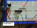
Check against my comment added to the attached copy of your photo.

There is no wire to the LED, nor a resistor in series with the LED and the transistor connections look very suspect.

I know you have stated you have wired as per the PICAXE manual but here is a sketch for an LED driver circuit that I have posted to others before.

Are you sure the transistor you have is a BC109. Not like the standard physical format I am used to seeing.
 

Attachments

Last edited:

westaust55

Moderator
Joe,

Last post for tonight . . (not on my PC so not able to draw a nice sketch)

See the attached sketch where I very roughly try to show you the position of component to drive the LED from PICAXE 18X output 4 (pin 10)

You do need to check the pin out for that transistor you have. My sketch is a guess.
 

Attachments

Joeroddis

Member
The picture is a little confusing, i'm going to draw one up. The thing in the top left is actually a 7805 voltage reg :)
 

Joeroddis

Member
Right, once and for all solved and it was nothing to do with my picaxe circuit.
As soon as i put two capacitors with the 7805 it started working perfectly!
Hahaha so much for the 'the 7805 needs no external capacitors because there are two inside' or whatever was said on the PDF.

I feel stupid now. :) Thankyou for your time everyone!
 

eclectic

Moderator
Joe.

Don't go away just yet.

As well as the 7805 capacitors,

1. 100nF capacitor near the Picaxe.
2. All the unused inputs need to be grounded.


They're topics that occur regularly.
They might not be needed today, but they will sometime.

e.
 

hippy

Ex-Staff (retired)
We're into the realm of what must be, what should be, and what can sometimes be ignored.

In many cases caps either side of the 7805 aren't needed, nor are decoupling caps and inputs can be left floating ... but not in every case.

Doing it properly should be a case of doing it by the book, making the design robust to start with and removing things which turn out not to be needed. Reality is that most hobbyists ( myself included ) start with the bare minimum, hope it works, and usually it does ( or more correctly, seems to ). Unfortunately it's easy to start thinking it will always work and forget that it may not !

I'm not sure the Rev-Ed PDF's have said caps aren't needed with a 7805 because they are included but I may be wrong; I think that's referring to three-pin resonators.
 

Dippy

Moderator
Joe,

Can you show which manual/page where it says that no caps are needed for the 7805 please ? - as this could be important. We don't want anyone else to get misled.

Certainly Manual 1 page 21 shows caps on the 7805.
Generally for all devices you should read the Data Sheet as goodness knows how many manufs are making that old regulator. And no doubt there are several difernt cap specs too.

Anyway, if you could let everyone know where it says no caps are needed then it would be very handy.
 

Dippy

Moderator
Well found sir!

Really the point I was making was that as 'every man and his brother' makes 7805s it would be a worrying statement to say in a general manual that no caps are required.
That's what I'd like Joe to highlight.

You can now safely go the pub eclectic and I promise not to tell anyone that you spend hours looking for Data Sheets - besides it would be pots and kettles if I did :)
I'm off to the pub shortly so we'll keep our Senior Anorak status a secret.
 

westaust55

Moderator
7805 Voltage Regulator - need for capacitors

On the referenced datasheet, on Page 2 “Electrical Characteristics”, note 2 makes reference to all reading being made with a capacitor across the input and across the output. The schematic on the datasheet does not show internal capacitors.

Looking at the Fairchild datasheet from http://www.datasheetcatalog.com/datasheets_pdf/7/8/0/5/7805.shtml
Pages 21 onwards show these two capacitors for most “normal” circuit applications.

Over the past 20 or 30 years of using the 7805 regulators have never built or seen a basic voltage regulating circuit that does not include these capacitors.
 

westaust55

Moderator
driving and LED from PICAXE output

Joe,

As mentioned yesterday, I can see no sign of a resistor between the PICAXE output and the LED.

The LED works from a reduced voltage, typically 1.2 to 2.5V for normal 5mm diam LEDs, and these have a maximum current rating of 20mA.

The PICAXE Outputs are rated at 25mA each and in the On (HIGH) state will be close to Vdd (+4.5V or 5V). Therefore if directly connected to an LED can can supply excessive current for both components.

A current limiting (aka voltage dropping) resistor should be used. a Value of around 330 Ohms will be suitable for most applications.
 

Joeroddis

Member
Really good point about the 7805s, it seems that when you looks across different datasheets, things are ever so slightly different. I'm not sure but when i think of 7805, i think ST so that might be the make of it :)

westaust55: they are 5v LEDs so they don't need a resistor, thanks for pointing this out though, because i have a bunch of normal LEDs and would have just assumed they didn't need a resistor because the other ones didn't, even though this is basic ohms law. I think sometimes when you are in the heat of things, you sometimes forget little things :)
 

Dippy

Moderator
Joe: "Hahaha so much for the 'the 7805 needs no external capacitors because there are two inside' or whatever was said on the PDF"

Well I'm still waiting for Joe to point out which data sheet said no capacitors were required because there are two inside... it seems to have gone a bit quiet.
Please let us know as soon as you can.

Joe, you say you think it is an ST regulator. I've just taken a quic squiz at 2 ST data sheets for that device. BOTH suggest values for bypass/compensation/input/output capacitors (tke yr pick on terminology).
I found a useful paragraph in the 'ON Semi' MC78xx range:
In many low current applications, compensation
capacitors are not required. However, it is recommended
that the regulator input be bypassed with a capacitor if the
regulator is connected to the power supply filter with long
wire lengths, or if the output load capacitance is large. An
input bypass capacitor should be selected to provide good
high-frequency characteristics to insure stable operation
under all load conditions. A 0.33 F or larger tantalum,
mylar, or other capacitor having low internal impedance at
high frequencies should be chosen. The bypass capacitor
should be mounted with the shortest possible leads directly
across the regulators input terminals. Normally good
construction techniques should be used to minimize ground
loops and lead resistance drops since the regulator has no
external sense lead.

The above would apply to a number of devices though values may be different.
Re: Capacitors:-
The moral is 'fit and forget'. Suitable values of course Sherlocks.
Moral Generally:-
ALWAYS read the actual device Data Sheet from manufacturer (sometimes pointless on Ebay purchases :) hence my aversion to be a skinflint)

So, if you next question refers to actual electrical spec of a PICaxe chip you'll know where to look....
 
Last edited:

moxhamj

New Member
Re "Page 1, near the top."

The reference says that a cap on the input isn't needed unless the reg is a long way from the supply capacitor. So that implies that there is still some sort of supply capacitor. The cap might be 470uF or similar with a diode bridge and transformer. But if battery powered, I would still suggest a supply cap anyway.

As for the output side - 0.1uF caps are always a good idea - at least one across the picaxe power supply and then one across every 3-4 other chips. I tend to put them across every chip - I bought a whole batch once and they cost 1c each so for 1c per chip I can be sure no transient faults will reset chips etc.

Then there are caps like a 22uF tantalum on the output side. Maybe these are not needed. But all the professional boards I have hacked have them included (indeed, I have never had to buy any coz all mine are recycled). So if the pro's use them, I'd use them too.
 

Joeroddis

Member
Dr_Acula is right - "The reference says that a cap on the input isn't needed unless the reg is a long way from the supply capacitor."

Which i just assumed meant you didn't need one.
 
Top