clamping input signal from 7.4v ???

tony_g

Senior Member
i have to adapt one of my circuits for my brother to use in one of his rc models.

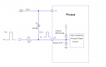
i use the circuit thats going to be altered for him at 5v but now have to read an rx signal from an aux channel at a system voltage of 7.4v, i have already redesigned the circuit with a 5v regulator for the picaxe chip but after reading an earlier thread by marmitas and seeing suggestions about using a zener clamp i just need some advice as thats new territory for me, up until now i have never used these above 5v and after reading this thread:

http://www.picaxeforum.co.uk/showthread.php?25166-Reading-pulses-from-a-Radio-Control-receiver

i now know i need to clamp the input signal.

i have looked around and tried to find info but it still seems strange to me, im not getting the whole idea how it works and if i need to calculate correctly what rating/type the diode/resistor needs to be to keep the input signal in a tolerable voltage range given the 7.4v system setup he's running.


tony
 

premelec

Senior Member
I gather you only need to clamp small currents... you could use a zener diode or adjustable 'zener' shunt regulator like TL431 [q.v.] putting a resistor in series with the source signal to limit current flow to the zener... The zener simply goes between PICAXE input pin and V- to limit voltage. A voltage divider of 2 Rs could also be used...
 

Goeytex

Senior Member
I suggest you use the same clamping method used in the Picaxe download circuit, only add an external diode to improve clamping. See the attached diagram.

When the voltage at the input pin reaches +V (5.0v) the diode begins to conduct. At 5.2v the diode goes into saturation. This prevents the voltage at the I/0 pin from increasing past 5.2volts as the current is shunted back to the positive supply. The 22K resistor limits current to about 200 microamps through the diode with a 7.2v input. The diode will only need to dissipate about 150 microwatts of power (average). Therefore a small diode will work fine. A Bat85 diode is commonly used.

A Bat85 Schottky is rated at 200 milliamps and is more than adequate. It works better than the internal ESD diodes which by themselves will clamp the input to ~5.5v which is very close the to the absolute maximum allowed.
 

Attachments

tony_g

Senior Member
thank you premelec and goeytex, i can now alter my pcb gerber files and get the slightly modified boards fabbed.

i knew sooner or later i would have to look at changing my board layouts for running from higher voltages and signals, thankfully to remain in the safe zone for the picaxe it does not require my boards to really be changed too much at all.

thanks for the help guys.

tony
 

Paix

Senior Member
Is there any benefit to adding a 10k resistor from the left hand end of the resistor (as viewed in your diagram) to the 0V rail, or would that serve no purpose as we don't anticipate negative voltages which we might possibly anticipate in the download circuit?

I think personally that you have opened up some fairly closed thinking and this bit of level translation has become ubiquitous and not just for downloading any more . . .

Wx in TX looking good :)
 

MartinM57

Moderator
The main function of the 10k resistor is/would be to make sure that the PICAXE input is tied to ground (well, through 32k of resistance) when the input is open circuit - it doesn't affect the ability of the circuit to handle negative voltages.

Negative voltages in the download circuit are handled by the lower internal ESD diode in the PICAXE - if you're paranoid about things, you may want to put a BAT85 between the pin and ground (pointy end to pin), paralleling the internal diode.

Note that the internal diodes are called "ESD" - electro static discharge - their primary purpose is protection from higher voltage transients, not necessarily constant external voltages higher than Vcc ... although a lot of people rely on them for that
 

jojojo

Senior Member
Take care with this schematic.

In my mind, it woud be better with zener connected to groud.
Else case, output voltage would be upper than 5 V.

See simulation :

zenerprotec.jpg
 

MFB

Senior Member
These are more of a general comment on input clamping. Although zener diodes can protect against excessive positive voltages (and anything over about minus 700mV) but tend to have soft turn-on characteristics at low current. For digital inputs this is not normally a problem but can result in significant errors if feeding an analogue input. For digital and analogue input protection there can be an additional problem in that the relatively low values of zener series resistor can power the PICAXE when it's supply is shut-down before that of the input circuitry.

All the above problems can be avoided by buffering the PICAXE input with a rail-to-rail I/O opamp that's configured for non-inverting and has a high value input series resistor.
 

hippy

Technical Support
Staff member
In many cases a simple current limiting resistor is all that is required. The clamping diodes within the PICmicro are usually rated at +/-20mA and inputs signals will register correctly with far lower currents supplied. Note though that some inputs do not have clamping diodes to +V and in those cases an external diode does need to be connected if voltages higher than +V are applied.

It is recommended practice to use external clamping diodes and zener diodes or use a potential divider to limit the voltages to within the specification range. Many people however leave these out and do so without reporting any observable adverse effects.
 

AllyCat

Senior Member
Hi,

MFB is correct to draw attention to the fact that the "Knee" of "Zener" diodes (particularly the lower voltage versions) is very far from "ideal".

But why make it so complicated? A single high-value resistor (100k or maybe even 1M) between the higher voltage signal(s) and the PICaxe input pin(s) is all that's needed to connect a digital signal.

If you're paranoid (or as hippy indicates, just for the case of the "input only" pin), then add a (schottky) diode between the pin and the Vcc rail. And if you're totally, totally paranoid then add another resistor of the equivalent value from Vcc to ground (just in case the PICaxe is "asleep" and there is absolutely NO other current drain on the supply rail).

Cheers, Alan.
 

srnet

Senior Member
But why make it so complicated? A single high-value resistor (100k or maybe even 1M) between the higher voltage signal(s) and the PICaxe input pin(s) is all that's needed to connect a digital signal
Could not agree more.

And to boot the simple resistor (and possibly an extra schottky clamp diode) will protect the PICAXE pin even if the supply voltage changes, which can happen of course.
 

MFB

Senior Member
My general comments included the clamping of analogue inputs, for which anything over a 10K series resistor would be ill advised. I don't see that adding a non-inverting opamp with a single series resistor is that complicated (or expensive) considering you can get four in a DIL package.
 

tony_g

Senior Member
well certainly lots of "food for thought" on this but all good reading and new information to digest,

thanks,

tony
 

Dippy

Moderator
Sometimes there is confusion/overlap between simple level-shifting and spike/transient/ESD protection.

Generally speaking, for a known Vin digital sensing, we can use voltage divider , zener (as described) or clamping as described.
Where appropriate we can add isolators, buffers and transistor clamping.
Even with buffers you may have to protect them from nasties - so back to clamping.
For analogue sensing (e.g. ADC) the zener method is usually off the menu for reasons already mentioned.

We have to be careful with diode clamping and restricting current to low levels.
Transistor clamping won't impact on the power supply line.

But sometimes when signals get fast (e.g. high-speed serial) we have to get our calculators out rather than selecting 'gut feeling' resistor values.
This is due to stray and input capacitances forming an RC and distorting the wave-shape.
If you round-off your digital too much then the receiver can get confused.
This probably has no relevance in this case but should be stored in the grey cells for the future.
So, horses for courses too.

Good luck :)
 

MFB

Senior Member
All useful comments. Regarding the use of non-inverting rail-to-rail I/O opamps for buffering, there is normally no need for additional clamping because their high impedance inputs allow the use of a high value series resistor (>100K) that protects against excessive input voltage. I have not yet managed to damage opamps used in this configuration and (until the output is within a few tens of mV of either rail) not introduce noticeable 10-bit ADC errors.
 

Dippy

Moderator
Well, I was trying to make a very general point and not criticising your suggestion.
Some op-amps will latch or die if not used properly and I was also trying to include 'nasty spike' consideration.

Many novices (and I include my younger self in this) will use any dusty old op-amp without really determining suitability or full consideration of the circuit/application/behaviour.
And if the 'worst case' is built into the design then the chance of failure is reduced.

Anyway, I'll exit the world of op-amps now and have some lunch.
 

MFB

Senior Member
Quite agree that dusting off an old 741 for example could lead to no end of confusion, like changing output inversion when overloaded. A common mistake when using opamps in the non-inverting configuration is forgetting to select a rail-to-rail INPUT type and not just rail-to-rail output.

Lunch sounds like a good idea. Enjoy!
 
Top