Circuit not working

CLUELESS1

Senior Member
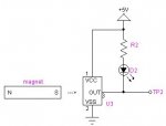
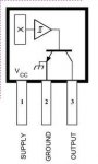
There will be a Picaxe in this, but this circuit worked on breadboard but now making a neater job it does not work. Really desperate to get working as for an elderly relative who gets off his chair without the carer seeing. It has a hall effect switch which when a magnet moves away is triggering events. It did have a relay to put power on external circuitry, but I tried to use a BD140 as a switch. I have checked my board, even put breadboard together and it fails, desperate to find why and get working.

circuit.jpg

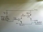
Really appologise for scrappy circuit

I know the output from the hall switch is happening, but not further down
 
Last edited:

AllyCat

Senior Member
Hi,

"Not working" and "Hall switch" is not very informative, but from the circuit diagram, the things I would try are:

Is the BD140 wired correctly with the collector in the middle (and I can never remember myself which side is the emitter)?

Is the Hall output really getting close to ground (zero volts)? I would try a resistor across one of the base-emitter junctions, probably about 1k or 2k2 across the base-emitter of the BC337.

Note that the circuit can be given a "snap" action (technically called hysteresis) by connecting a high value resistor (at least 100k) from the BD140 collector to the BC337 base (or maybe the Hall output pin).

Cheers, Alan.
 

CLUELESS1

Senior Member
Thanks Alan, I will have a play as suggested. So hot in here my heads going inside out. Checked BD140 wired correctly. Seems always the way, throw something together it works, build it neatly does'nt work.
 

CLUELESS1

Senior Member
After ages tearing hair out, I found if I put a 1k resistor between pin 3 of hall switch to ground it works? Be happy if I knew why.
 

AllyCat

Senior Member
Hi,

I've just noticed the "A3144" at the side of the drawing. That device appears to have an Open Collector output, so needs a Pull Up resistor (perhaps 10k) from the output to the supply (pin 1).

As it's a Unipolar type, it's important that the magnet is oriented correctly, which will depend on its exact shape and type. Also, note that your transistors will (should) turn OFF when the magnetic field is strong enough.

Cheers, Alan.
 

bluejets

Senior Member
Hall switch
pin 1 is supply......don't need 100R
pin 2 is ground
pin 3 should have pull up to positive rail about 10k

Should also have a pull up resistor on collector of bc337

hall switch turns on and turns off bc337 (base to ground) which allows bd140 to turn on (pnp ..base now high through extra resistor)
 

Attachments

CLUELESS1

Senior Member
Many thanks everyone, now that explains the problems.

I was following this circuit for the hall switch, and as I did not want an LED shown, I did not realise I was omitting a method of pullup.

Hall1A3144.jpg

Added with other bits pointed outnow sorted out.
I have learnt something as well as looking for more information, NEVER TAKE BREADBOARD TO PIECES until final end product works, thanks all again.
 

srnet

Senior Member
I have learnt something as well as looking for more information, NEVER TAKE BREADBOARD TO PIECES until final end product works, thanks all again.
I dont leave bread boarded circuits in place.

But then I draw circuit diagrams and build a breadboard circuit from that.
 

Dippy

Moderator
I agree; pen/pencil & paper & datasheets first. Plus calculator.
Far easier to get preliminary circuit on paper before bending lots of legs ;)
Then breadboard and feedback any required changes to sketch.

Straight to breadboard, esp. for a novice, relies more on luck.
Less time is needed on the Forum waiting for help and a little cicruit will be up & running by the time your coffee has cooled.
And then you will have a documented working circuit to build from.

The only bits where I agree with Clueless's "NEVER TAKE BREADBOARD TO PIECES" is:
a) If you envisage some mods/additions to circuit.
b) Double-double-checking sketch with reality (i.e. breadboard).
 

CLUELESS1

Senior Member
Thanks both. I had scribbled down a circuit, so few components. Built it on plug in breadboard, it worked so put it on veroboard, failed.

Rebuilt plug in board, this time did not work, added pullups, worked, modified my vero, worked. Very greatful, thanks
 
Top