CHI-030 Programme Board analogue input issue

Snowghost

New Member
Hello All
Im Posting here as many others do, when scratching ones head begins to leave marks.

Simple Project outline : Energise a Relay, when a SLA 12v Battery is full, De-energise the same relay when the battery is flat.
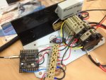
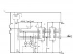
Input Components : CHI-030 Programme Board, 180k Ohm/560k Ohm Resistor bridge. 5v UBEC (rc) voltage regulator.

Readings:
PICAXE supply Voltage = 5 Volts.
Battery = 12.something Volts
Middle of Resistor bridge to -Vcc = 3.something Volts

Code Snipit:
Symbol InputPin = 0 `Rename pin17, the input pin
Symbol Voltage = b0 `Rename Variable b0

readadc InputPin,Voltage `read the batt voltage through divider and input 0
sertxd( #Voltage,CR,LF ) 'send value on input pin to computer via download cable


ISSUE

with the input pin (the middle connection to input 0 on the programming board) connected to the middle of my resistor divider, the value it spits back is 18,17,20,16...etc.
I am expecting this to be higher, something around the 100 - 200 mark, is that correct?
with the input pin floating, it spits back 0.
with the input pin connected to -vcc it spits back 0
with input pin connected to +5v it spits back 255.


if some one could please give me some information on how to do this that would be greatly appreciated :)
and feel free to ask me any more questions.


thanks
Michael.
 

hippy

Technical Support
Staff member
The board has a 10K pull-down on the pin you are reading and 560K paralleled with 10K = ~10K, so your divider is more 180K/10K than 180K/560K.

Use the 10K as the bottom resistor, then just add an appropriate top resistor, greater than 15K for 12V to produce 5V input.
 

westaust55

Moderator
It does pay to consult the relevant rev Ed board datasheets. A full list is available via the "Manuals" link in the black toolbar at the top of these PICAXE forum pages.
Specifically for the CHI030 board datasheet see here: http://www.picaxe.com/docs/chi030a.pdf

On page 7 there is a schematic and the 10 kOhm resistor mentioned above by hippy can be seen as resistor R8 at the left side of the schematic diagram.

Is your PICAXE chip an older 18X or a newer 18M2 part.
Although many things will work correctly, for the newer parts it is good practice to use the port.pin nomenclature as per the Rev ed documentation.
So what is input 0 with an older part is identified as C.0. Using "0" alone may/will be confused with pin B.0 on the M2 and X2 parts.

Noting that you have not posted on the forum for around 3.5 years, it is feasible that you have an older chip.
In case you need the older version of the CHI030 datasheet to match an older PICAXE chip t can be found here: http://www.picaxe.com/docs/chi030.pdf
 
Last edited:

Snowghost

New Member
The Chip is a 18X
R8 has been removed.
read through the CHI030 document.

haha yeah its been a while - i see things in this project and think "oh gosh, thats where i went wrong when i was trying to do this/that/other thing"

could you please tell me what page thats on about this c.0 and b.0 stuff? thanks


The only other thing that i cant be sure of is that the 0v of my UBEC is connected to all other 0v... nodes. (the voltage between the two was zero, but what i need to do is measure measure the resistance between 0v in and 0v out of the UBEC.)
I am finding it hard to explain, but do you see where im going here? my reference voltage is not good?

I know what you are saying though hippy, it defiantly looks like its being tied to ground, but yep, the PCB has i nice R8 showing.


Attached is the code iv worked on so far - im sure there are lots of different and better ways of doing things, but im relearning as i go :)


Thanks
 

Attachments

westaust55

Moderator
could you please tell me what page thats on about this c.0 and b.0 stuff? thanks

PICAXE manual 1 page 72: http://www.picaxe.com/docs/picaxe_manual1.pdf

PICAXE manual 2 (V7.9) page 27: http://www.picaxe.com/docs/picaxe_manual2.pdf
also mentions on page 87, 107, 143

ALso mentioned in the M2 briefing note/ addendum: http://www.picaxe.com/docs/picaxem2.pdf
However to avoid confusion it is strongly recommended that new programs should always be written using the
new PORT.PIN notation.
Keep in mind the Port.Pin notation is recommended for the newer M2 and X2 parts
 

hippy

Technical Support
Staff member
R8 has been removed.
Are you sure ? 12V through a 180K over 10K divider would give around 0.6V which would give a READADC reading of about 30 which is in the ballpark to the results you are getting.
 

Snowghost

New Member
Yep, very sure.
still have had no luck
take a look at the photo, see what you think - ive been messing around with the negitive leads trying to get something to work.....

perhaps my chip is buggered?
photo of board.JPG

Thanks
 

Snowghost

New Member
so ive done more tinkering:
I fed my resistor bridge into analogue input pin two, and measured the voltage, (3.2v)
then i changed the program to read the pin two.......and it gets sucked down to a few millivolts.


what is this telling me?


Thanks guys

Michael,.
 

hippy

Technical Support
Staff member
what is this telling me?
That there's something wrong with the way things are wired up or in your code.

Take the resistors and 12V out of the equation and test with a 1K, 4K7 or 10K pot across +V/0V with its wiper to the analogue input you are reading. Does that read 0 to 255 as you vary the pot ?

Perhaps post your code so we can cast an eye over it.
 

Snowghost

New Member
I will see what i can find to do that for you.

I posted the code above. and can you see from the photo anything wired up obviously wrong?
 

inglewoodpete

Senior Member
560k and 180k are many times too high in value. Try 10k (top resistor) and 4.7k (bottom resistor)

Edit: If the input voltage will never go above 12 volts, the top resistor could be reduced to 6.8k ohms
 
Last edited:

Snowghost

New Member
im reading voltages of an SLA so they could go as high as 15 if something is wrong.

anyway PROBLEM SOLVED
new chip in the mail, reads real goodddddddddddddddddddddddddd
thanks for all ye help, im sure il come back in the future!!
 

Snowghost

New Member
Actualy.....Pete......could these values be causing a poor impedance match to my Picaxe-18X
as ive just found another 18x in the draw (looks new by the package) and getting the same result.
yet it works with the picaxe 18M2 that arrived in the mail the other day.


i dont have many resistors on hand - il have to get some.
 

inglewoodpete

Senior Member
......could these values be causing a poor impedance match to my Picaxe-18X
as ive just found another 18x in the draw (looks new by the package) and getting the same result.
yet it works with the picaxe 18M2 that arrived in the mail the other day.
"560k and 180k are many times too high in value" means the same as "causing a poor impedance match".:) If the 18M2 works OK, then it's ADC input impedance must be quite a lot higher than the older 18X - the technology is about 8 years younger. 560k is very high unless you only want to pass a micro amp or so. It is quite rare that you would use a resistor that 'big' anywhere in electronics.
 

Snowghost

New Member
Premo - thanks for that Pete.
yeah they were the best ones in the draw at work (railways) gna have to find a new draw :p and put the 18x to work, save the M2 for something else :p


While im here - can anyone point me in the direction of a code snipit for taking sample readings, for some more acuracy. i can repeat the readadc command with diffrent words to write to, then devide by the times ive done it, but thats messy looking.


thanks again
Michael.
 

Snowghost

New Member

westaust55

Moderator
Changing the resistors may help - but no guarantee.

I notice from the past program code you posted the code relates to a solar panel and 12 V SLA battery.
Is the panel and charger connected to the battery when you have done these tests?
Some solar panel to battery chargers use PWM and thus there are on and off periods which will alter the battery surface charge.

What happens if you temporarily connect a capacitor, say 1 uF, across the PICAXE ADC input to filter/stabilise the voltage? DO you still see the 0.5 Volt swings?
 

Snowghost

New Member
thats a very, very good point West, and that may work in anycase.
the tests have been done during the day....but its the same at night with nothing coming out of the charge controller.
a list of readings, no load, at night : 13.19v, 12.96v, 12.69v, 12.81v, 13.23v, 13.12v, 12.97v ....etc.
 

Snowghost

New Member
just came accross the "case" commands, made short work of my code.
havnt been able to mess with my resisters yet thow.
 
Top