Thought I'd post my first finished picaxe project here to give back for all the help I found throughout here.
I will layout the whole project here and a link to my website which has a the step by step and more pictures if you are interested in seeing more (I realize my site also has stuff for sale but please know I am not trying to make a quick buck here. I fell in love with electronics and any money I make is to only support my new love.)
To help keep Lucy, my daughter, and Papa connected on a more regular basis he got us both a webcam. This was amazing. We already had a computer hooked up to our LCD in the living room so the whole family could chat and being able to see each other on the big screen was great. Except if you know kids then you know how long they will actually sit in one place for the camera. About 30 seconds! My wife or I would constantly be getting up to follow Lucy around the living room with the camera as she showed Papa her rocking horse over there, and her toys in the toy box over here, and then this on the other side. You get the point. So born from a very real need came this following project which we still use to this day. We call it Cammy (you know, 'cause everything you tell a kid HAS to end in “e”: blanky, raggy, dolly, booby- my wife hates that last one).
Aside from the servos, this project barely costs over $10, and you can use any remote that has Sony code. For us, I just programmed an extra function button to switch to Cammy control and then picked the buttons I wanted to use to control it. I will show you how to do exactly the same thing; it really is very easy. On with the project...
Picture of finished project here
Complete project with more pictures & action video here.
Assembly:
Parts List: Cammy Parts
1 x Picaxe 08M
1 x IR Receiver
2 x Mini Servo (Hobby Store)
1 x 2 X 3 project board
1 x Project case (Radio Shack)
1 x Bracket for camera to servo
1 x 8 pin DIP socket
3 X 330R Resistor
1 x 220R Resistor
1 x 4.7K Resistor
2 x .01uF Capacitor
1 x Female USB plug
2 x 3 pin male headers
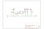
Schematic is here
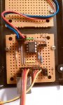
I’m going to leave you to get all the parts put together on the board, just use the schematic and start with one piece at a time. Once you get everything soldered in place, lets go ahead and program our chip.
Programming:
Code can be found at the end of this post.
Download the code and open it in your programmer. Before we send this to our Picaxe, we need to figure out what the button codes are for your remote. The nice thing about the Picaxe chips is their built in IR receive functions to accept any Sony Code. If you are going to use a universal remote, then pick the function button you want to use, like VCR or something.Then, using your remotes manual, program it to use any Sony device. Now we are going to use our new board and Picaxe to tell us what the button codes on our remote are. Plug in a USB cable to power the board, then plug in your programming cable. Next uncomment the code where it says uncomment (2 lines). Now go ahead and program the chip with this code. When done you should see the debug window pop up. Go ahead and point the remote at the IR Receiver and press a button. What does the debug window say for b13? If you see no change then something is wrong. Otherwise the number you see is the button code. Go through each button you want for the following functions: Up, Down, Left, Right, Center, Full Left, Full Right. The last 3 are great for getting somewhere quick, like chasing your kid from one side to the other.
Once you have the button numbers, enter them in to the code corresponding to their function under 'IR Remote Button Data' and comment out the 2 lines from before. Now program your chip and see what it does. It should move the servos. You may need to swap the left and right numbers to adjust to the mirror effect.
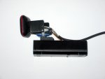
Constructing the Bracket:
Constructing the case and bracket to fit the camera took a bit of thinking through. Ever camera is going to be a bit different and might be a bit challenging to solve but I believe you can do what it takes to get it worked out. Check the pictures of my Cammy to maybe spark some ideas for yours. Also Sparkfun offers a pan/tilt bracket for about $6 that works great as well.
Conclusion:
I hope you find this project useful as my family and I have. If you have any questions ask away, I'll do my best to answer them. Please know that I am by no means an expert or professional and only know what I know from pouring over this forum and the good ol' internet. Suggestions and creative criticism are more than welcome. Also I have already completed the initial work on Cammy v.2 which brings IR learning mode on an 18M2 Picaxe to make programing the remote of your choice even easier. Stay tuned for that release as well.
I will layout the whole project here and a link to my website which has a the step by step and more pictures if you are interested in seeing more (I realize my site also has stuff for sale but please know I am not trying to make a quick buck here. I fell in love with electronics and any money I make is to only support my new love.)
To help keep Lucy, my daughter, and Papa connected on a more regular basis he got us both a webcam. This was amazing. We already had a computer hooked up to our LCD in the living room so the whole family could chat and being able to see each other on the big screen was great. Except if you know kids then you know how long they will actually sit in one place for the camera. About 30 seconds! My wife or I would constantly be getting up to follow Lucy around the living room with the camera as she showed Papa her rocking horse over there, and her toys in the toy box over here, and then this on the other side. You get the point. So born from a very real need came this following project which we still use to this day. We call it Cammy (you know, 'cause everything you tell a kid HAS to end in “e”: blanky, raggy, dolly, booby- my wife hates that last one).
Aside from the servos, this project barely costs over $10, and you can use any remote that has Sony code. For us, I just programmed an extra function button to switch to Cammy control and then picked the buttons I wanted to use to control it. I will show you how to do exactly the same thing; it really is very easy. On with the project...
Picture of finished project here
Complete project with more pictures & action video here.
Assembly:
Parts List: Cammy Parts
1 x Picaxe 08M
1 x IR Receiver
2 x Mini Servo (Hobby Store)
1 x 2 X 3 project board
1 x Project case (Radio Shack)
1 x Bracket for camera to servo
1 x 8 pin DIP socket
3 X 330R Resistor
1 x 220R Resistor
1 x 4.7K Resistor
2 x .01uF Capacitor
1 x Female USB plug
2 x 3 pin male headers
Schematic is here
I’m going to leave you to get all the parts put together on the board, just use the schematic and start with one piece at a time. Once you get everything soldered in place, lets go ahead and program our chip.
Programming:
Code can be found at the end of this post.
Download the code and open it in your programmer. Before we send this to our Picaxe, we need to figure out what the button codes are for your remote. The nice thing about the Picaxe chips is their built in IR receive functions to accept any Sony Code. If you are going to use a universal remote, then pick the function button you want to use, like VCR or something.Then, using your remotes manual, program it to use any Sony device. Now we are going to use our new board and Picaxe to tell us what the button codes on our remote are. Plug in a USB cable to power the board, then plug in your programming cable. Next uncomment the code where it says uncomment (2 lines). Now go ahead and program the chip with this code. When done you should see the debug window pop up. Go ahead and point the remote at the IR Receiver and press a button. What does the debug window say for b13? If you see no change then something is wrong. Otherwise the number you see is the button code. Go through each button you want for the following functions: Up, Down, Left, Right, Center, Full Left, Full Right. The last 3 are great for getting somewhere quick, like chasing your kid from one side to the other.
Once you have the button numbers, enter them in to the code corresponding to their function under 'IR Remote Button Data' and comment out the 2 lines from before. Now program your chip and see what it does. It should move the servos. You may need to swap the left and right numbers to adjust to the mirror effect.
Constructing the Bracket:
Constructing the case and bracket to fit the camera took a bit of thinking through. Ever camera is going to be a bit different and might be a bit challenging to solve but I believe you can do what it takes to get it worked out. Check the pictures of my Cammy to maybe spark some ideas for yours. Also Sparkfun offers a pan/tilt bracket for about $6 that works great as well.
Conclusion:
I hope you find this project useful as my family and I have. If you have any questions ask away, I'll do my best to answer them. Please know that I am by no means an expert or professional and only know what I know from pouring over this forum and the good ol' internet. Suggestions and creative criticism are more than welcome. Also I have already completed the initial work on Cammy v.2 which brings IR learning mode on an 18M2 Picaxe to make programing the remote of your choice even easier. Stay tuned for that release as well.
Code:
output 1                    	'Setup pins 1 & 2 as output pins for servos
output 2					'
input  3			   		'IR input pin
output 4					'LED or optional pin i/o

symbol spospan = b1          	'Servo Position holder for pan servo
Symbol spostilt = b2         		'Servo Position holder for tilt servo


symbol servo1 = 1           	 	'Pan Servo
symbol servo2 = 2           		'Tilt Servo
symbol led = 4		     		'LED
symbol servomin = 80         	'Servo minimum travel 75 is typical min
symbol servomax = 220        	'Servo maximum travel 225 is typical max
symbol deadctr = 140         	'servo 1 & 2 center position
symbol fulllt = 80           		'full right servo position - adjust for your full left button, max is still servomin-max from above
symbol fullrt = 220          		'full left servo position - adjust for your full right button, max is still servomin-max from above
symbol panspeed = 7        		'adjust this for speed of pan servo 2-10 is nominal
symbol tiltspeed = 2        		'adjust this for speed of tilt servo 2-5 is nominal

;// IR Remote Button Data - adjust numbers acording to your remote found by debugging buttons
symbol inclt = 52            		'Left Button Increment
symbol incrt = 51            		'Right Button Increment
symbol posrt = 96            		'Full Right Position
symbol posctr = 101          		'Center Position
symbol poslt = 99            		'Full Left Position
symbol incup = 117           		'Up Button Increment
symbol incdown = 116         	'Down Button Increment

spospan = deadctr			'Set pan servo to dead center position
spostilt = deadctr			'Set tilt servo to dead center position

main:

	setfreq m4
	pulsout servo1,spospan      'Send new position to pan servo
	pulsout servo2,spostilt    	'Send new position to tilt servo
	high LED
	infrain2                   		'wait for new signal from remote
	;debug infra               	'uncomment to debug remote buttons
	;goto main                  	'uncomment to debug remote buttons
	setfreq m8
	low LED

	if infra = incrt then 	  	'the following finds out what button was pushed then assigns the proper servo pulse to holders spospan & spostilt
		spospan = spospan+panspeed min servomin max servomax
	elseif infra = inclt then
		spospan = spospan-panspeed min servomin max servomax
	elseif infra = incup then
		spostilt = spostilt+tiltspeed min servomin max servomax
	elseif infra = incdown then
		spostilt = spostilt-tiltspeed min servomin max servomax
	elseif infra = posctr then
		spospan  = deadctr min servomin max servomax
		spostilt = deadctr min servomin max servomax
		goto posctrsub
	elseif infra = poslt then
		spospan = fulllt min servomin max servomax
		goto posltsub
	elseif infra = posrt then
		spospan = fullrt min servomin max servomax
		goto posrtsub
	end if
	goto main

posrtsub:
	for b0 = 1 to 17           	'start a loop long enough to get the servo from one side to the next
		setfreq m4			'Sets Frequency to 4Mhz
		pulsout 1,fullrt    	'move to central position
		setfreq m8			'Sets Frequency to 8Mhz
		pause 20            	'wait 20ms
	next b0
	pause 20
	goto main

posctrsub:
	for b0 = 1 to 10         	'start a loop long enough to get the servos centerd
		setfreq m4			'Sets Frequency to 8Mhz
		pulsout 1,deadctr    	'move to central position
		pause 20
		pulsout 2,deadctr    	'move to central position
		pause 20            	'wait 20ms
		setfreq m8			'Sets Frequency to 8Mhz
	next b0
	pause 20
	goto main

posltsub:
	for b0 = 1 to 17         	'start a loop long enough to get the servo from one side to the next
		setfreq m4			'Sets Frequency to 4Mhz
		pulsout 1,fulllt       	'move to central position
		pause 20            	'wait 20ms
		setfreq m8			'Sets Frequency to 8Mhz
	next b0
	pause 20
	goto main
Attachments
-
 73.1 KB Views: 68
 -
 30.1 KB Views: 51
Last edited: