Hi,
For some time I've had an un-assembled AXE171 Audio Kit "On the Shelf" waiting for a project which might need it. That time hasn't arrived yet, but a RECENT THREAD made me look into its capabilities: The kit doesn't appear particularly appropriate for that project (possibly best done with a modest, SIM-less smartphone) because the SPE035+14M2 seem more relevant to (automated) Sound Effects and short voice messages, etc. But also, its .WAV fie format is "lossless", which implies that, if required, it should be possible to encode and store some relevant (and/or an enormous quantity of) "Data", probably using PICaxe's RFOUT or HSEROUT commands. This would be recovered from the Player's file(s) using PICaxe's complementary commands in the 14M2 and stored in the up to 500 bytes of indirect RAM (@bptrinc).
The first modification I propose is to move the TX-RX signal on the H1 connector from B.4 to probably B.1. That frees up the I2C bus SDA data line (B.4), to be connected to an additional pin at the end of the "LCD" connector (in one corner of the 14M2's PCB). The I2C bus can expand its capabilities enormously, firstly to drive a traditional parallel interface 1602 / 2004 LCD or OLED display (via an "I2C backpack"), or more conveniently one of the tiny OLED "graphics" displays which use the SSD1306 (or SH1106) controller chips. The 14M2 is particularly suited to driving these chips, with its 2 x 512 bytes of Table EEPROM (including the second Program Slot) to store Font Data. An I2C RTC (Real Time Clock) module can add the capability of a Talking (or Chiming) Timepiece, and many other I2C Environmental sensors, up to a fully Alarming or Talking Weather Station, etc.. Also an I2C Serial EEPROM (e.g. 24LC64, perhaps on the RTC module) can access much more Readable and/or Writable Memory, e.g. for data logging.
There may be (many) occasions when this "Player module" is required to be physically small, so my next proposal is to assemble the two boards "back-to-back" (i.e. solder sides inwards). This can reduce the whole assembly to less than 5 cms square; smaller than the (included) 3 x AA battery pack, if used. The key alignment reference would be the H1 header pins, which could employ the supplied socket, or use directly soldered pins (perhaps even with the plastic spacer removed to reduce the thickness slightly), or flexible wires to act as a "hinge" to ease servicing, etc.. The normal H1 connector position is slightly "inboard", but there is a "partial" group of pads near to the edge of the PCB. These align the edges of the boards better, requiring the drilling of just one hole in the corner (and another for the new SDA pin of the LCD header). Any undesired track links can be broken by a pair of parallel knife cuts, with the intervening copper "popped-off" using a hot soldering iron tip, or maybe ground away when drilling the additional required holes.
The SPE035 Player board would be at the "Front", to give easy access to the SD Card Reader and the 3 push-buttons. The additional button on the 14M2 board need not be fitted, or it might be linked instead directly to pin C.5 (the Programming input) to act as a Hard Reset (unless a DISCONNECT has been programmed). Similarly, a rear-facing LDR may not be very useful, so can be omitted, at least from its intended location. The (different) "SW1" buttons on the two boards almost align back-to-back, so are a convenient location for any additional board-to-board interconnects, particularly as the switches have 4 pins, but only 2 connections are required. Thus, there is scope to cut tracks to give an isolated link, but beware that the switches themselves have linked pins. Also the button on the 14M2 board is connected to the Supply Rail, whilst the SPE035 buttons connect to Ground:
It is planned to connect one of the Audio outputs through to Pin C.0, which is an input to one of the PICaxe's internal Comparators, having its output on C.1. That might be used to extract/slice data from the Analogue waveform, but it is not clear (i.e. not tested) whether RFIN or HSERIN can read directly from that output pin, or must be externally linked to another (input) pin. For reference, RFIN can receive up to around 2,000 bits/second (fixed at 4 MHz), whilst a customised HSERIN protocol might be usable at up to around 20,000 baud (at SETFREQ M32).
The SPE035 board is significantly "wider" than the 14M2 board, but the extended width carries few components so might be cut off, or drilled to carry a few custom components. The speaker could be mounted without overhanging the edge of the board, or there should be space for a USB or Audio (3.5mm) socket, or even my favourite PAM8403 Stereo amplifier module. This amplifier chip has Standby and Mute capabilities (which might be driven by B.5 or another pin), but some modules do not bring them out to a terminal. Like the SPE035 itself, this amplifier uses an "H-Bridge" output configuration (to give a greater output voltage swing) but for more detail I may update my thread referred to in THIS LINK.
The 14M2 board is significantly "taller" than the Player board, but this is an ideal position to locate a 32 x 128 pixels SSD1306 OLED display, on the REAR of the board, where even the LCD/I2C pin sequence is correct (but check Vdd and GND carefully). This location is immediately above the push-buttons so there is the opportunity to Label them as "soft" keys with Icons and/or a Font ranging from 8 "Big" (16 x 32 pixels) ASCII characters up to a full 4 rows of 21 (or more) characters (including simple "proportional spacing"). There is space for the LDR or a LED beside the Display (again mounted on the rear of the 14M2 board) to facilitate automatic control of the OLED's brightness. The LDR is an obvious choice, but for many years I've been intrigued by Wilf_NV's PICaxe "LED Firefly" which uses a single LED to emit and detect light. That worked down to "night" light levels, but here we just need to increase the Brightness when in full daylight. Another (untested) idea for extending the "User Interface", is that if the SPE035 is set to play one from a group of "Silent" (or Muted) tracks, then the PICaxe can detect if any of the "transport" buttons has been pressed (and for how long), by reading the present Track Number, Playing Time and Volume registers via the $4x commands.
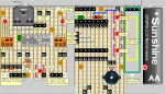
AFAIK, there is no published circuit diagram for the AXE171 Kit, so to assist the modified construction, I have copied the PCB layouts into a "Pebble" layout, attached below, but of course the vertical "Vero" copper strips should be ignored. The scale and position of components is not perfect, because some pads and components are not arranged on a 0.1 inch grid, but the general layout and function/name of most pin/pad connections should be apparent. For example, "Test-Sockets" represent (unused) Pads, White pin headers show "new" holes, and Grey wires indicate an electrical connection. The boards are shown side-by-side (to fit the PC screen), but would be connected end-to-end with the 14M2 board folded backwards by 180 degrees (i.e. inverted) to put its H1 pins at the top. Then the whole module rotated by 90 degrees to put the display at the top (normally), although this bit-mapped OLED can be configured for most character orientations.
Cheers, Alan.
For some time I've had an un-assembled AXE171 Audio Kit "On the Shelf" waiting for a project which might need it. That time hasn't arrived yet, but a RECENT THREAD made me look into its capabilities: The kit doesn't appear particularly appropriate for that project (possibly best done with a modest, SIM-less smartphone) because the SPE035+14M2 seem more relevant to (automated) Sound Effects and short voice messages, etc. But also, its .WAV fie format is "lossless", which implies that, if required, it should be possible to encode and store some relevant (and/or an enormous quantity of) "Data", probably using PICaxe's RFOUT or HSEROUT commands. This would be recovered from the Player's file(s) using PICaxe's complementary commands in the 14M2 and stored in the up to 500 bytes of indirect RAM (@bptrinc).
The first modification I propose is to move the TX-RX signal on the H1 connector from B.4 to probably B.1. That frees up the I2C bus SDA data line (B.4), to be connected to an additional pin at the end of the "LCD" connector (in one corner of the 14M2's PCB). The I2C bus can expand its capabilities enormously, firstly to drive a traditional parallel interface 1602 / 2004 LCD or OLED display (via an "I2C backpack"), or more conveniently one of the tiny OLED "graphics" displays which use the SSD1306 (or SH1106) controller chips. The 14M2 is particularly suited to driving these chips, with its 2 x 512 bytes of Table EEPROM (including the second Program Slot) to store Font Data. An I2C RTC (Real Time Clock) module can add the capability of a Talking (or Chiming) Timepiece, and many other I2C Environmental sensors, up to a fully Alarming or Talking Weather Station, etc.. Also an I2C Serial EEPROM (e.g. 24LC64, perhaps on the RTC module) can access much more Readable and/or Writable Memory, e.g. for data logging.
There may be (many) occasions when this "Player module" is required to be physically small, so my next proposal is to assemble the two boards "back-to-back" (i.e. solder sides inwards). This can reduce the whole assembly to less than 5 cms square; smaller than the (included) 3 x AA battery pack, if used. The key alignment reference would be the H1 header pins, which could employ the supplied socket, or use directly soldered pins (perhaps even with the plastic spacer removed to reduce the thickness slightly), or flexible wires to act as a "hinge" to ease servicing, etc.. The normal H1 connector position is slightly "inboard", but there is a "partial" group of pads near to the edge of the PCB. These align the edges of the boards better, requiring the drilling of just one hole in the corner (and another for the new SDA pin of the LCD header). Any undesired track links can be broken by a pair of parallel knife cuts, with the intervening copper "popped-off" using a hot soldering iron tip, or maybe ground away when drilling the additional required holes.
The SPE035 Player board would be at the "Front", to give easy access to the SD Card Reader and the 3 push-buttons. The additional button on the 14M2 board need not be fitted, or it might be linked instead directly to pin C.5 (the Programming input) to act as a Hard Reset (unless a DISCONNECT has been programmed). Similarly, a rear-facing LDR may not be very useful, so can be omitted, at least from its intended location. The (different) "SW1" buttons on the two boards almost align back-to-back, so are a convenient location for any additional board-to-board interconnects, particularly as the switches have 4 pins, but only 2 connections are required. Thus, there is scope to cut tracks to give an isolated link, but beware that the switches themselves have linked pins. Also the button on the 14M2 board is connected to the Supply Rail, whilst the SPE035 buttons connect to Ground:
It is planned to connect one of the Audio outputs through to Pin C.0, which is an input to one of the PICaxe's internal Comparators, having its output on C.1. That might be used to extract/slice data from the Analogue waveform, but it is not clear (i.e. not tested) whether RFIN or HSERIN can read directly from that output pin, or must be externally linked to another (input) pin. For reference, RFIN can receive up to around 2,000 bits/second (fixed at 4 MHz), whilst a customised HSERIN protocol might be usable at up to around 20,000 baud (at SETFREQ M32).
The SPE035 board is significantly "wider" than the 14M2 board, but the extended width carries few components so might be cut off, or drilled to carry a few custom components. The speaker could be mounted without overhanging the edge of the board, or there should be space for a USB or Audio (3.5mm) socket, or even my favourite PAM8403 Stereo amplifier module. This amplifier chip has Standby and Mute capabilities (which might be driven by B.5 or another pin), but some modules do not bring them out to a terminal. Like the SPE035 itself, this amplifier uses an "H-Bridge" output configuration (to give a greater output voltage swing) but for more detail I may update my thread referred to in THIS LINK.
The 14M2 board is significantly "taller" than the Player board, but this is an ideal position to locate a 32 x 128 pixels SSD1306 OLED display, on the REAR of the board, where even the LCD/I2C pin sequence is correct (but check Vdd and GND carefully). This location is immediately above the push-buttons so there is the opportunity to Label them as "soft" keys with Icons and/or a Font ranging from 8 "Big" (16 x 32 pixels) ASCII characters up to a full 4 rows of 21 (or more) characters (including simple "proportional spacing"). There is space for the LDR or a LED beside the Display (again mounted on the rear of the 14M2 board) to facilitate automatic control of the OLED's brightness. The LDR is an obvious choice, but for many years I've been intrigued by Wilf_NV's PICaxe "LED Firefly" which uses a single LED to emit and detect light. That worked down to "night" light levels, but here we just need to increase the Brightness when in full daylight. Another (untested) idea for extending the "User Interface", is that if the SPE035 is set to play one from a group of "Silent" (or Muted) tracks, then the PICaxe can detect if any of the "transport" buttons has been pressed (and for how long), by reading the present Track Number, Playing Time and Volume registers via the $4x commands.
AFAIK, there is no published circuit diagram for the AXE171 Kit, so to assist the modified construction, I have copied the PCB layouts into a "Pebble" layout, attached below, but of course the vertical "Vero" copper strips should be ignored. The scale and position of components is not perfect, because some pads and components are not arranged on a 0.1 inch grid, but the general layout and function/name of most pin/pad connections should be apparent. For example, "Test-Sockets" represent (unused) Pads, White pin headers show "new" holes, and Grey wires indicate an electrical connection. The boards are shown side-by-side (to fit the PC screen), but would be connected end-to-end with the 14M2 board folded backwards by 180 degrees (i.e. inverted) to put its H1 pins at the top. Then the whole module rotated by 90 degrees to put the display at the top (normally), although this bit-mapped OLED can be configured for most character orientations.
Cheers, Alan.