Breadboarding Tools - Simple Logic Probe

Mycroft2152

Senior Member
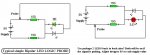
Multi-meters are very handy, but sometimes you only need a quick check of the logic level. This is where a Logic Probe is used

This is a simple to build Logic Probe. A resistor, LED, a BIC pen body and some wire is all it takes.

This is a golden oldie, I think I first saw the design in one of Don Lancaster's Cookbooks.

It is not a cure-all, but gives a quick indication of a high state on a pin. One note of caution, it can load the circuit, so use it on outputs only.

There are a number of other excellent probe circuits out there. A bit more complicated, but without the possibility of loading the circuit under test. PHAnderson has a slick design using a PICAXE 08 that also captures pulses. With a bit a of shoehorning, it will fit in a pen body too (my next build).

Myc
 

Attachments

steliosm

Senior Member
Very nice idea :)
I never had a logic probe and ever since I saw PHAnderson's code I always wanted to make one.
I have a small maxim box from samples laying around, I could probably use that to host the circuit and your BIC pen case for the probe...
 

manuka

Senior Member
Mmm- great that its in such a nifty container, but maybe a bit TOO simple I'm afraid! Although numerous "pulse grabber" work-arounds exist, IMHO even the most bare bones DIY logic probe needs suitably coloured LEDs to show the distinctive Hi/Lo states. Otherwise you may simply have a non contact open circuit. I've a huge stack of simple probe circuits - want more pointers? Stan
 

Mycroft2152

Senior Member
Stelios:

Take a walk through your local office supply store, you'll find hundreds of different pens in all shapes and sizes. "magic Marker" bodies make great logic probes as they have enough room inside to add just about anything. Just be creative!

Stan,

An internet search results in dozens of circuits for logic probes, What you build depends on the functions, your skill and the availible parts.

Much depends on the packaging that you desire. Personally, I like a self contained probe.

With some creativity, discretes and ic's can be fitted into a pen body. With ic's, folding the legs underneath will reduce the size considerably.

Your display is also a matter of personal preference, a single LED, dual color leds, or even 7 segment LEDs can be used. With a 7 Segment LED even a "H" or "L" can be displayed.

I've had quite a few over the years, both commercial and home made, one of the most usefull had a buzzer rather than an LED as the indicator. When you are probing the leg of an ic you don't really want to shift your gaze to see the LED.

Of course all of these were pre PICAXE. I seems it would be pretty simple to add to PHAnderson's PICAXE 08 LOGIC Probe design to include both the H/L display and buzzer. Of course . all in a pen body.

Just build one, logic probes are very handy breadboarding tools.

Myc
 

manuka

Senior Member
Google is your friend- logic probe circuits abound! Educationally the old 2 LED "back to back" (or single bipolar LED ) approach has considerable barebones mileage. As well as the differing LED brightnesses & working voltages (Red ~ 1.8V, Green ~ 2.0V), application HI/LO thresholds may need considering of course => www.interfacebus.com/Chart_Low_Voltage_ICs.gif - just tweaking R values usually handles all these. IMHO simple logic work can usually forgo pulse stretching circuitry. Stan
 

Attachments

Last edited:

Tom2000

Senior Member
One of the handiest tools in my kit is a cheap eBay logic probe with an audible output. I'm always amazed at the convenience of making quick checks "eyeballs off."

I bought one of Peter Anderson's 18X Picaxe experimenter boards. I spiffed it up with a few extra components that I had lying around. One was a bipolar red/green LED. I connected a pair of 680 ohm resistors between +5 and ground, with the bipolar LED taken off the center tap of that voltage divider. It makes a nifty poor man's logic probe, distinguishing between high, low, and open states. For a pulse train, the LED's color gives me some idea of the duty cycle.

(If I was going to do it again, I'd set the voltage divider values empirically to balance out the LED's brightness for high and low states. Matched resistors don't give me matched brightness.)

In any case, it's not a perfect logic probe, but it's really handy, and can't be simpler. For onboard test equipment, it's great.

Tom
 

hippy

Technical Support
Staff member
I never tested 08/08M/14M but those should and the 18X can be configured to detect any change on input pins by poking SFR's so they can be used to detect pulses far shorter than a PICAXE normally could.
 

hippy

Technical Support
Staff member
I don't have my notes to hand but they can do "interrupt on pin change" and ( at least the 18X ) "interrupt on RB0". They don't have to invoke an actual interrupt which would likely crash the firmware, but the hardware can be configured as needs be and the "interrupt flags" which indicate the interrupt would have occured if enabled can then be read from the PIR (?) register.
 
Top