late_voyager
New Member
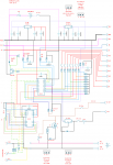
just for info anyone bored and find faults?
Here i have the schematic for my project.
24v battery supplying 12v to 5v, for project and outputs for all
numerous 5v inputs, for switches
triggering 24v out, detecting and measuring a external 24v input
Here i have the schematic for my project.
24v battery supplying 12v to 5v, for project and outputs for all
numerous 5v inputs, for switches
triggering 24v out, detecting and measuring a external 24v input
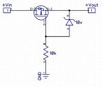
") I had drawing wrong for reverse protection. (what do people use for drawings, cant find decent and cheap with most components)
I had drawing wrong for reverse protection. (what do people use for drawings, cant find decent and cheap with most components)