Bluetooth >>> Picaxe

slimplynth

Senior Member
Hello

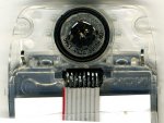
Nervously about to attempt to solder connections to one (spare tester) of these...

http://www.sure-electronics.net/rf,audio/GP-GC021_Ver1.0_EN.pdf
picture on pg. 4

(nervous because 13 quid seems like a bad omen)

If anyone is interested in doing the same I became aware of these units from...

http://hackaday.com/tag/gp-gc021/ Using the circuit diagram linked...


I've never done any surface mount soldering.. I've googled a bit (relatively) the tutorials are aimed at soldering smd chips that have legs, albeit smaller than the picaxe etc im used to.

The current plan, because its for the blimp is to don my magnifying headset and kynar/solder the necessary connections. This may work if i manage a clean job...

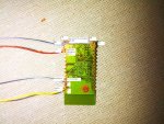
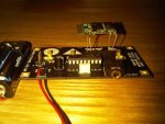
The bluetooth RC car project page...

http://uzzors2k.4hv.org/index.php?page=blucar

photo's show what his finished board looks like

I was hoping someone could give me advice, thank you.. please.. or shall i just forge ahead an use the Kynar.
 
Last edited:

slimplynth

Senior Member
am goosed then :) i've set it up an keep coming back to it... just struggling to make that first move.. ate a bag of monstermunch in preparation.. doesn't seem to have helped

Update: trying karma by drinking a bottle of "oranges & lemon" by "This Water"... which apparently will give one person in Malawi clean drinking water for a month. Worth a shot...
 
Last edited:

eclectic

Moderator
am goosed then :) i've set it up an keep coming back to it... just struggling to make that first move.. ate a bag of monstermunch in preparation.. doesn't seem to have helped

Update: trying karma by drinking a bottle of "oranges & lemon" by "This Water"... which apparently will give one person in Malawi clean drinking water for a month. Worth a shot...
Possible sensible suggestion, until one of the grown-ups arrives:

Ribbon cable, which has a 1.27mm spacing.
Use a wide wire stripper,
do not bare the ends,
solder tin the wires first.

Then try the clean-living bit. :)


e
 

Attachments

slimplynth

Senior Member
Possible sensible suggestion, until one of the grown-ups arrives:

Ribbon cable, which has a 1.27mm spacing.
Use a wide wire stripper,
do not bare the ends,
solder tin the wires first.

Then try the clean-living bit. :)


e
Cheers Ec. :D I would die without coffee though, im sure of it

I managed the first pad... the water is working :0)
 

slimplynth

Senior Member
Not sure it's really a finished project, is it? Am just about to try an get a simple LED flash test program working... a finished project, that would be a first for me :)

Still daunted by the prospect of eventually getting to the point of Blackberry >>> Picaxe <<< Blackberry comms. The 8900 supports the JSR-82 API so hopefully a simple led flash prog should be a starter for 10...

edit: have connected to the bt unit with hyperterminal
 
Last edited:

MartinM57

Moderator
Just about to get an 8900 myself (I note it has GPS as well) - I watch with interest...

I've absolutely zero idea how to write the Blackberry side of things though...
 

slimplynth

Senior Member
Now that is a great feeling :D

Used my new 18M2 Touch demo board to add the Bluetooth, solely for the the "B.4 LED" to light up whenever a preset character is recieved.. In reality I guess the operation is no different from the sparkfun 433 units... with the exception that these BT modules give rx/tx in one package and at the 3V that is required for the blimp.

I've only just set up the Rx (circuit diagram as per the original post to this thread with the obvious deletion/replacement of the competition's chip with an 18M2, wire from pin 1 of the BT module going to port C.0 on the touch demo board.) Powered from a CR-V3 battery. That's literally the complete setup.. the difficult part was soldering kynar to those tiny pads.

Code:
MAIN:

Serin C.0,N9600_8,b1
Debug b1
If b1=1 Then Goto LED    'b1=1 This equals key zero on your keyboard.
Goto MAIN

LED:
High B.4
Pause 10000
Low B.4

goto main
The BT module was easy enough to set up on my EeePC, with just power connected it was listed in the devices found.. set up as a virtual serial port on com12. Using Hyper Terminal for now to send characters.

Still have a minor headache with the comms, a repeat flaw in my understanding of hyperterminal/ascii codes/serial but the penny will drop again after another brew.. by using the debug screen in the PE I was able to specify that a keypress (b1=1) = the zero key on my keyboard... It's not perfect and its better that i admit that I have not done all my homework than let someone point it out to everyone :) anyway that issue aside..

I'm still happy to see an LED light up, repeatedly, on command when I press the magic key "0".. an awesome feeling in fact (Glad I went to bed when i thought I'd overcooked it)
 

Attachments

slimplynth

Senior Member
It's important to note that the data sheet for these BT modules states that comms is only possible between an embedded unit and a pc... i.e. you cant put one BT module on one picaxe and have it communicate with another picaxe with a BT unit. Well that's how I read it but then i don't see it as a limitation because pc >>> picaxe >>> pc if fine for me. Perhaps possibility to overcome this would be to create your own software for the BT comms to bridge the gap between Picaxe >>> Picaxe BT comms. easy enough on paper though :rolleyes: as always.
 

Attachments

hippy

Technical Support
Staff member
As best I can tell the Bluetooth modules use a 'UART' protocol so that would normally require a Txxxx baud rate on the PICAXE.
 

slimplynth

Senior Member
Cheers Hippy, will check that when I'm next home, thought I was makin mistakes with b1 and #b1 (with it working consistently, having debugged and settled on 'zero' as a test key)
 

slimplynth

Senior Member
Thanks Hippy :) you were right... Changed to T9600 and it works fine.

Code:
main:
Setfreq M8

Serin C.0,T9600_8,b1
'debug b1

Select b1
Case = 97  '"a" key
High B.4
Pause 5000
Low B.4

Case = 98  '"b" key
High B.5
Pause 5000
Low B.5

Case = 99  '"c" key
High B.6
Pause 5000
Low B.6

Case = 100 '"d" key
High B.7
Pause 5000
Low B.7

Else Goto main

Endselect

Goto main
I say "It works".. the connection is fine once it's established. Finding it has proven a little frustrating again tonight.

Not really sure what caused it to be found, in the last 40 mins - tried all manner of combinations of removing power, resetting laptop BT; different power supplies.. though when it did finally find/connect... the Blackberry's connection to the Laptop prevented it from completing the setup of the virtual serial port (Can anyone else see the iceberg coming)

Think it may be best to solder the other one onto a veroboard setup, to see if that fairs better. Still happy days..
 
Last edited:

slimplynth

Senior Member
Just about to get an 8900 myself (I note it has GPS as well) - I watch with interest...

I've absolutely zero idea how to write the Blackberry side of things though...
I did want to do it on the Blackberry but after speaking about it with a friend from uni days, who's an iphone app developer.. im tempted to sell my soul to the apple :eek:.. still the 8900 runs java apps so finding info shouldn't be too difficult.

Apologies if my first effort at a tutorial is not up to scratch.. but here is my fullest account of what I did.
 

Attachments

dsvilko

Senior Member
I am interested in adding bluetooth support to my Picaxe and was very much encouraged by this thread!
While looking around the Ebay for inexpensive bluetooth modules I came across this one:
http://cgi.ebay.com/2-PCS-Wireless-Bluetooth-RS232-TTL-Transceiver-Module-/200523926482?pt=LH_DefaultDomain_0&hash=item2eb0284bd2
It's half the price (twice the modules actually) of the one suggested in this thread and has a lot more features. It can act as a master so can connect to another module and is fully configurable through AT commands. You also get 12 programmable IO ports.
Is anyone willing to have a look at the module documentation:
http://www.sendspace.com/file/yyu4vy
and tell me if there is any obvious (or not so obvious) reason why it would be a bad idea? I currently have no experience with Picaxe wireless communication other than the IR.
 

slimplynth

Senior Member
Thanks for posting that - think this is the datasheet for it..

http://mdfly.com/newmdfly/products/RF2.4G/MDRS232WM/RF-BTMZ417.pdf

The original ebay link you posted went to a downloading site and as it's a works PC I thought best not to.

That does sound much better if it negates the PC master; the QnA at the bottom suggests this is so.

Code:
Q: Hello. Is it possible to pair two of those modules to each other without a PC?
A: Dear egor_m, You can use a MCU or ARM processor to control it. This module is the transparent wireless module to send 232 TX/RX data via Bluetooth connection. Have a nice day! Nina
See the description section in this link...
http://www.mdfly.com/index.php?main_page=product_info&cPath=8_47&products_id=64&zenid=iptf99tbn1c0gv89ojad8c4q56

This is exactly what I was looking for in the first place - Cheers, Hopefully be able to buy some of these next month. Bluetoothe as easy as the 433 Rx/Tx modules and probably less prone to error (famous last words)
 

dsvilko

Senior Member
I don't think that's the same module. They certainly look different and AT commands are also different.
Here is sheet for the one I found (uploaded to my site):
http://domjan.fizika.org/BC4.zip
As you can see, the list of the supported AT commands is quite extensive. You can configure baud-rate, master/slave/slave-repeat mode, change the device ID, scan and identify other bluetooth devices, turn on/off 12 IO ports (so you wouldn't even need the Picaxe to do some simple things) and a lot more.
It certainly seems wonderful on paper. By default it's in the slave mode (9600N1) so should be equally simple to program as the module you are using.

Did you solve the quirks with the device discovery on your module? Would you still recommend it?

EDIT:
Your module and the one I found are actually pin-compatible :) Hopefully this module should work just as good but with a lot of added features that can be used if required.
 
Last edited:

slimplynth

Senior Member
Cheers for the Link DS.

It would be wrong for me to be saying they are rubbish, I haven't tested anywhere near enough to make a judgement. (finish for christmas on 17th December, so hoping to get a good week or two of tinkering in)

Of the two I bought, I've found that once it's connected it's stable but making the connection can be frustrating - combinations of power up/discovery for Lappy and BT module seems hit an miss.

A steady voltage supply seems to be critical, they worked best (for me) with a CR123 battery. It's really a nice feeling to even switch on an LED from the laptop.. no wires or cables etc. I really wanted to control it from my blackberry, got started with the IDE for the Curve 8900... really slick but they want $20 for access to the bluetoothe part of the API. (Hopefully Tmobile or O2 will eventually give me an 'HTC Desire')

As for your original question.. at those prices I'd say go for it if you can afford it. I bought two because the soldering was difficult for my coffee/beer diet shaky hands.
 

dsvilko

Senior Member
Hmmm... I was hoping you got your module working reliably. Maybe the problem is on the PC side? I am using a cheap Nokia S60v3 phone so shouldn't have much trouble with programming - there is a Python interpreter for Symbian phones with full phone API access, including bluetooth :)
With bluetoothed Picaxe you basically get a free wireless high-resolution LCD that's easy to program and obviously doesn't tie up a ton of Picaxe pins. It certainly seems extremely useful. I think I'll get the module and see how it goes.
 

slimplynth

Senior Member
The problem I had was getting the device discoverable, that's checking on both an Asus HA1008HA and a Blackberry 8900 - both of which have always served well wirelessly.

It was a bit frustrating because there's not really a lot to check, 4 wires and a few bridged pins. I would prefer a breakout module for peace of mind with the connections. There's not (wasn't) a great deal of help to get started and no advice on troubleshooting.

The one good thing is you only need power to be connected for it to be discoverable.
 

dsvilko

Senior Member
Looking at the documentation of these two different modules it would certainly seem that the ones I found were put together by the same manufacturer as yours. One is just a stripped down version of the other so any problems you are having have a high probability of being present in the 'BC4' modules as well. :( Also, with the added complexity there is a lot more possibility for error. Still, it is cheaper :) There is also a possibility of connecting two led indicators to the module for hopefully more 'debugging' info.
 

slimplynth

Senior Member
Have got one new module left in the packet, hoping tonight to have a better diy breakout board.

Just about to get an 8900 myself (I note it has GPS as well) - I watch with interest...

I've absolutely zero idea how to write the Blackberry side of things though...
Martin, did you get a 8900?

http://devsushi.com/2007/11/15/getting-started-with-the-blackberry-java-development-environment-jde/

I found this site very helpful in getting started with the Blackberry programming. Still think that Android and an HTC desire would be the better option though, given the tutorials available on Hackaday

Just wish I could get T-mobile to give me one
 

slimplynth

Senior Member
dag dam it! I'd been waiting 666 all week then missed it :)

Edit: It is weirdly funny - I was just about to start on a breakout veroboard but now have doubts.
 

MartinM57

Moderator
Martin, did you get a 8900?
...I found this site very helpful in getting started with the Blackberry programming...
I did. Blooming thing - can't get away from work emails now :(

So many things to do, so little time. Current project is to teach myself C for AVRs. Have at last come across an IDE with some libraries that I can live with (£££s for the full version though - get what you pay for etc) and have been trying to wire the part of my brain that deals with C pointers, since it wasn't wired at birth.

Transferred a middling complexity assembly code AVR project to C - about 10% bigger code size but a helluva lot easier and quicker to understand/maintain/enhance now I've got me head around extern's, include's, void's, separate c files in a project, volatile variables etc
 

slimplynth

Senior Member
Your head sounds like a mess :D I thought I was havin it bad.. recently trying to juggle my day work and getting a database up and running at the same time to control one of our processes.

You're right about the email, it's a curse really, too easy to check and usually too late at night to do anything about the problem.
 

slimplynth

Senior Member
It's working much better, replaced kynar with legs/wire from some sacrificial signal diodes. It connects quite nicely to a header on PortC of the 18M2 touch demo board. The serin is now C.5


Code:
MAIN: 
Setfreq M8 
Serin C.5,T9600_8,b1 'has to be set to T9600 not N9600 (cheers Hippy) 
'debug b1 
Select b1 
Case = 97 '"a" key 
High B.4 
serout C.6,T9600_8, ("Light one on")
Pause 5000 
Low B.4 
serout C.6,T9600_8, ("Light one off")

Case = 98 '"b" key 
High B.5 
serout C.6,T9600_8, ("Light two on")
Pause 5000 
Low B.5 
serout C.6,T9600_8, ("Light two off")
Case = 99 '"c" key 
High B.6 
serout C.6,T9600_8, ("Light three on")
Pause 5000 
Low B.6 
serout C.6,T9600_8, ("Light three off")
Case = 100 '"d" key 
High B.7 
serout C.6,T9600_8, ("Light four on")
Pause 5000 
Low B.7 
serout C.6,T9600_8, ("Light four off")
Else Goto main 
Endselect 
Goto main
The setup is running fine from 2 AAA batteries, was probably my dodgy soldering at the root cause of it not connecting reliably. I've cycled the power a few times and it reconnects ok (manually).

Range:

Range will be affected by your own surrounding but approx..

Indoors:

the signal strength when the laptop is only 1ft is showing as only 'Good'. Just tested it from

Lounge >>> Kitchen
Wooden door/wall/doorway) approx 5m as a blind crow would fly.. the connection strength drops to weak.

Outside:

Will test it outside when it's gone dark and the LEDs are bright enough to see.

From lounge >>> outside
 

Attachments

Last edited:

slimplynth

Senior Member
Changed the code above to return an LED status message. The connection was lost when the voltage reached 2.6V.

Don't have any new AAA batteries to test with but with two older batteries from an LED torch (reading 2.9V)...outside - los, the connection was good for approx 40ft. At which point the LED status message was no longer returned but it was already difficult at about 30ft to see the dim LED light on the 18M2 side; at about 40ft I thought I could still see it lighting up but that might be my over optimistic mind playing tricks again.

BT ideas/daydreams:

BT Tea/Coffee Maid - Bluetooth any hot drink order
 

dsvilko

Senior Member
So, the problem was in the wiring? That sounds wonderful!
Also, the four-legged module walking on your board - LOL! :)
Hope I'll have as much luck with my module.
 

slimplynth

Senior Member
Yeah the problem looks to have been the wiring, further root cause analysis has deemed my laziness to be at blame :).

N.B. It's not a good idea to leave it 'walking' the dev board either; took it to work and the serin leg broke off leaving the solder pad completely unusable - not too bothered by this though because I assumed yesterday it would break during the practise run.

Still it was tricky (imo) so not really looking forward to veroboarding the second one. They should use that as a game in 'The Cube'.
 

Haku

Senior Member
I bought a couple of these BT modules because I thought they could talk to each other - http://cgi.ebay.co.uk/110623162275 - but it looks like they can only talk to a host *facepalm*, so I ordered a couple of XBee Pro modules.

Anyhow, the BT modules arrived today and as I have them I might as well get them going, I soldered a couple of wires to the +3.3v & GND lines, using two strands of a high-speed IDE cable because it's tiny and solid core, powered up the module but it can't be discovered on a WinXP machine - am I doing something wrong?
 

dsvilko

Senior Member
I bought a couple of these BT modules because I thought they could talk to each other - http://cgi.ebay.co.uk/110623162275 - but it looks like they can only talk to a host *facepalm*, so I ordered a couple of XBee Pro modules.
The ones I have found (and ordered - should arrive in a couple of days, hopefully) should be able to talk to each other and to any SPP compatible bluetooth device as they can work both as a slave and as a master. They are not even much more expensive. I know it doesn't help you much but still :)
Will share my first impressions when the modules arrive. I already have a simple break-out board ready :)
As for the second part of your post, I have got no idea. Most of these modules shoulb be discoverable with just power connected. Have you tried scanning with your mobile phone?
 

Haku

Senior Member
My mobile isn't fancy enough to have BT ;)

I know the BT dongle on the PC works as it picks up my BT enabled multimeter, and when I put a 'spy camera finder' next to the dongle when it's scanning for new devices the indicator LED blinks like mad, but putting the 'spy camera finder' next to the BT module when it's first turned on and when the PC is scanning for new BT devices, the indicator LED doesn't blink at all.

I'll try powering up the 2nd bt module later tonight.
 

slimplynth

Senior Member
Hi Haku.. try soldering all connections, see jpg in post 14.. power up and should be discoverable.

EDIT: are they the same modules as mine...
 
Last edited:

Haku

Senior Member
I wired power to the 2nd module and during various testing managed to get them recognised by the host PC, individually and both at the same time showing up as separate devices.

The problem was power, with my digital control bench PSU set to 3.3v and using it's on/off output button the BT module doesn't seem to like that, but putting a mechanical switch between the PSU & BT the module powers up properly.

Looking at the amps/watts display on the PSU I now realise it's easy to figure out when the BT module is running properly, when it was using a steady 10mA it wasn't running properly, but wavering between 10 & 30mA means it's running properly.

Now to figure out what I can use them for :D
 
Top