Bipolar Stepper, manual 3 query

ZOR

Senior Member
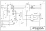
Can someone help me understand this circuit in Manual 3. It makes no reference to what Picaxe this is shown for. I tried to marry up Pins 4,5,6,7 with pin layouts but could not identify.

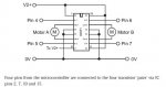
Also as this is described as being for a bipolar stepper, why is the drawing marked Motor A and Motor B, as though for two motors, but my stepper has two coils.

It probably is me with basic knowledge that cannot fathom it out

Thanks

BIPOLAR.jpg
 

ZOR

Senior Member
Many thanks eclectic, appreciate you coming in with that.

Have a good Christmas, hope the people are nice back!!

Best Regards
 

bfgstew

Senior Member
ZOR, the '2 motors' A and B represent the 2 coils of the bipolar stepper motor. And as @e pointed out, use any 4 pins to control them........:D
 

ZOR

Senior Member
Many thanks bfgstew for confirming that. I will mark my drawing as Coil A and Coil B. Have a good XMAS and new year
 
Hi! Zor
I know just how you feel; when I first started getting involved with PICAXE and bipolar motors I found the manual more confusing than watching an episode of “Soap”! But stick with it, the manuals are an invaluable source of knowledge, well at least they are once you have mastered “Picaxe speak”.
I have posted a schematic that I hope will help it shows a hook up to a 28X1, only because I had a number of those given to me, and as “bfgstew” said any 4 output pins should work. There’s also a bit of code that should drive your motor clock and anticlock by making the appropriate pin high.

Turntable motor control.jpgView attachment Stepper motor off pin 0.bas
 

ZOR

Senior Member
Many thanks for the information and schematic, very useful for getting me started.
As you say the manuals are invaluable, it's just sometimes the need to interpret bits needs a bit more exploring before going ahead. Probably the IC will drive two motors, don't know, hence given Motor A and B.

Never mind, can now start breadboarding it tomorrow. All the best for XMAS and new year.
 

SAborn

Senior Member
Its often a wise move to read the data sheet for the driver chip you are using, look up the L293 data sheet as it will help you understand better what you are trying to do, and they normally give several setup examples.

With stepper motors i find its a good practice to use a 330R resistor on all logic pins between picaxe and L293, it should work without them but, can solve some intermitting problems for the cost of a few cents in resistors.

The first schematic you posted dont show the enable pins used on the L293, its also a good practice to control the enable pins with the picaxe as well, this allows you to turn off all motor outputs, which should be done prior to a direction change etc.
 

ZOR

Senior Member
Many thanks Saborn for the added useful information. My schematic was lifted straight from the manual. All the best
 
Top