Battery charger issue

sniper887

Member
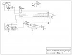
I'm getting strange behavior with this NiMH battery charger circuit where it will start charge even with no battery inserted. It worked fine for months but a couple days ago started with this problem. I haven't yet removed the circuit board from the charger to debug and see what the ADC is doing, but I've seen similar problems and had it work by simply replacing the Picaxe. The supply voltage is supposed to be 5V but I have seen about 5.2V from the power supply. Either that is causing damage over time, or perhaps the battery positive connection to the ADC pin needs something to remove possible spikes. I have the 22K resistor there for that purpose, but that may not be working the way I think.

Code:
Code:
init:
setfreq m32
symbol battery = c.1
symbol currentsns = c.4
symbol pwmoutput = c.2
symbol led = c.0


symbol current = w0
symbol currentcount = w1
symbol currentsum = w2
symbol dutycyc = w3
symbol voltcount = w4
symbol volts = w5
symbol voltavg1 = w6
symbol voltsum = w7
symbol peakvolt = w8
symbol deltapeak = w9
symbol modulus = w10
symbol highvolt = w11
dutycyc = 0
current = 0
currentcount = 0
currentsum = 0
voltcount = 0
volts = 0
voltavg1 = 0
voltsum = 0
peakvolt = 0
deltapeak = 0


pwmout pwmoutput, 200, dutycyc 
low led

toggle led
pause 1000
toggle led
pause 1000
toggle led
pause 1000
toggle led
pause 1000
toggle led
pause 1000
toggle led
pause 1000
toggle led
pause 1000
toggle led
pause 1000
toggle led
pause 1000
toggle led
pause 1000
toggle led
pause 1000
toggle led
pause 1000

pause 16000


start:
gosub battdetect


main:


for voltcount = 0 to 199


modulus = voltcount // 5
if modulus = 0 then
	toggle led
endif


current = 0
gosub getcurrent


if current < 125 then
	dutycyc = dutycyc + 1 max 900
endif

if current > 125 then
	dutycyc = dutycyc min 1 - 1
endif

pwmduty pwmoutput, dutycyc


next voltcount

gosub getvolts
if volts < 100 then init
if volts > peakvolt then
	peakvolt = volts
	deltapeak = 0
endif

if volts <= peakvolt then
	inc deltapeak
endif
if deltapeak > 5 then endchg

debug
goto main

getcurrent:
fvrsetup FVR2048 ; set to 2.048V
adcconfig %011
current = 0
currentcount = 0
currentsum = 0
for currentcount = 0 to 49
pause 7
current = 0
readadc10 currentsns, current


currentsum = current + currentsum
next currentcount

current = currentsum / 50


return


getvolts:
fvrsetup FVR4096 ; set to 4.096V
adcconfig %011

volts = 0
voltsum = 0
voltavg1 = 0
pwmduty pwmoutput, 0

pause 8000

for voltavg1 = 0 to 19


readadc10 battery, volts 

voltsum = volts + voltsum
next voltavg1

volts = voltsum / 20

pwmduty pwmoutput, dutycyc


return

battdetect:
dutycyc = 500
pwmduty pwmoutput, dutycyc

gosub getvolts

if volts < 100 then start
dutycyc = 0
return

endchg:
pwmduty pwmoutput, 5

high led
  pause 8000
  gosub getvolts
  
  if volts < 100 then 
  	goto init
  endif
pwmduty pwmoutput, 0
pause 24000
debug
goto endchg
08m2 charger buck topo p mosfet copy.jpg
 

techElder

Well-known member
You didn't say enough about the power supply to make any conclusions, but a well regulated supply shouldn't have a problem staying closer to 5VDC.

A few points about the code.

1. There appears to be a trap at "If deltapeak > 5 then endchg".
2. The subroutine "battdetect:" has a goto "start" exit without encountering the return for that subroutine. My good friends on this forum say that is not a problem, but it is a sloppy exit from the routine.
3. IMHO I would change the initial "toggle led : pause 1000" to "for i = 1 to 12 : toggle led : pause 1000 : next i" . Maybe that's just me.
4. IMHO I would do a lot of indenting. That's how I saw item #1 and #2.
5. IMHO I would add a compiler directive for the PICAXE to use. We know its an 08 from the schematic, but ...

Perhaps these mean nothing to the normal operation of the code.
 

SAborn

Senior Member
More important what is the battery voltage?

You could add a zener diode to help protect the picaxe from over voltage on its input, but not a sure method, perhaps better to use a voltage divider and work with less resolution on the ADC input, but a broarder range of input voltage to suit.
 

sniper887

Member
The power supply is a 5v 6a switching type. The project has four circuits to charge 4 AA batteries, so it needed a fairly large power supply. Since each circuit charges a single cell, the voltage tops off at about 1.5 volts.
 

AllyCat

Senior Member
Hi,

5.2 volts is unlikely to cause any harm to, nor even a transient malfunction of, a PICaxe. But.....

Due to the location of diode D2, PinC.4 is measuring the average current through the FET (not the battery). Furthermore, I can't see what limits the current through the FET (or the battery), except for pure optimism that the software is operating as desired :confused:

Conversely, PinC.1 is measuring the battery voltage + a "random" element, depending on the phase of the PWM and the current in the FET. Averaging that "random" voltage over (apparently) 20 cycles is still likely to leave a random element, so I'm not surprised it the software occasionally does something "unexpected".

But sorry, with no comments in the code (except for two obvious lines), I really can't be bothered to try to work out what the program is actually doing, let alone what it was intended to do.

Cheers, Alan.
 

sniper887

Member
The current is controlled purely in the code, in a closed loop(measures the current and either increments or decrements the PWM duty as needed). There is no hardware current limiting, and that's why I used the buck topology for this circuit. You brought up a good point though, about the current measurement measuring average current through the MOSFET and not purely through the battery. Might be good to change that. As for voltage measurement I shut off the PWM right before reading the voltage, so really I didn't need the averaging routine for that. I would consider hardware filtering to deal with the ripple if I was measuring voltage with the PWM on.

Hi,

5.2 volts is unlikely to cause any harm to, nor even a transient malfunction of, a PICaxe. But.....

Due to the location of diode D2, PinC.4 is measuring the average current through the FET (not the battery). Furthermore, I can't see what limits the current through the FET (or the battery), except for pure optimism that the software is operating as desired :confused:

Conversely, PinC.1 is measuring the battery voltage + a "random" element, depending on the phase of the PWM and the current in the FET. Averaging that "random" voltage over (apparently) 20 cycles is still likely to leave a random element, so I'm not surprised it the software occasionally does something "unexpected".

But sorry, with no comments in the code (except for two obvious lines), I really can't be bothered to try to work out what the program is actually doing, let alone what it was intended to do.

Cheers, Alan.
 

AllyCat

Senior Member
Hi,

As for voltage measurement I shut off the PWM right before reading the voltage,....
Ah yes, I was thrown by the (presumably) spurious PWM updating here:
Code:
battdetect:
dutycyc = 500
pwmduty pwmoutput, dutycyc
gosub getvolts
It appears that you are measuring the battery voltage to 4 mV resolution and terminating the charge when it falls by 5 steps (i.e. ~20 mV). However, the normal figure for a single NiMH cell appears to be about -5mV, so I wouldn't expect the termination to be very reliable. Good data is hard to find, but this web link says:

An NiMH charger must be able to detect a voltage drop of around 5mV per cell. Therefore to reliably detect such a small voltage drop, sufficient noise filtering must be introduced into the NiMH charger to ensure that spurious pickup and other noise does not trigger the end of charge.

So you may need rather better hardware, but you could try intentionally introducing a small amount of analogue noise ("dither") into the voltage measurement and then accumulate a large number of readings to give a few extra bits of resolution. It's a method I've used with some success in my PICaxe battery capacity tester.

However, reliably charging NiMH cells just seems too complex for a simple (PICaxe) program. For example see Battery University or Microchip AN1384.

Cheers, Alan.
 

sniper887

Member
Hi,

Ah yes, I was thrown by the (presumably) spurious PWM updating here:
Code:
battdetect:
dutycyc = 500
pwmduty pwmoutput, dutycyc
gosub getvolts
It appears that you are measuring the battery voltage to 4 mV resolution and terminating the charge when it falls by 5 steps (i.e. ~20 mV). However, the normal figure for a single NiMH cell appears to be about -5mV, so I wouldn't expect the termination to be very reliable. Good data is hard to find, but this web link says:

An NiMH charger must be able to detect a voltage drop of around 5mV per cell. Therefore to reliably detect such a small voltage drop, sufficient noise filtering must be introduced into the NiMH charger to ensure that spurious pickup and other noise does not trigger the end of charge.

So you may need rather better hardware, but you could try intentionally introducing a small amount of analogue noise ("dither") into the voltage measurement and then accumulate a large number of readings to give a few extra bits of resolution. It's a method I've used with some success in my PICaxe battery capacity tester.

However, reliably charging NiMH cells just seems too complex for a simple (PICaxe) program. For example see Battery University or Microchip AN1384.

Cheers, Alan.
Just to clarify, the charge termination happens when the battery voltage has dropped by a step or more for 6 cycles. It's not looking for the total of 5 steps. Still I will look into the dithering thing, and the links you sent me (thank you for those by the way)
 

sniper887

Member
I had the wrong schematic and code since I have two designs of the charger (low-side-switch and high-side-switch). I reprogrammed the Picaxe and it works properly now. The difference is the circuit was actually the low-side-switch design.

The code that works:
Code:
init:
setfreq m32
;define pins
symbol lowbattery = c.1
symbol highbattery = c.4
symbol pwmoutput = c.2
symbol led = c.0
;define variables
symbol current = w0
symbol currentcount = w1
symbol currentsum = w2
symbol dutycyc = w3
symbol voltcount = w4
symbol volts = w5
symbol voltavg1 = w6
symbol voltsum = w7
symbol peakvolt = w8
symbol deltapeak = w9
symbol modulus = w10
symbol highvolt = w11
dutycyc = 0
current = 0
currentcount = 0
currentsum = 0
voltcount = 0
volts = 0
voltavg1 = 0
voltsum = 0
peakvolt = 0
deltapeak = 0


pwmout pwmoutput, 200, dutycyc 
low led

toggle led
pause 1000
toggle led
pause 1000
toggle led
pause 1000
toggle led
pause 1000
toggle led
pause 1000
toggle led
pause 1000
toggle led
pause 1000
toggle led
pause 1000
toggle led
pause 1000
toggle led
pause 1000
toggle led
pause 1000
toggle led
pause 1000

pause 16000


start:
gosub battdetect ;check voltage across battery leads

main:
;main loop
for voltcount = 0 to 199
	modulus = voltcount // 5
	if modulus = 0 then
		toggle led
	endif


current = 0
;current control loop
gosub getcurrent

if current < 48 then
	dutycyc = dutycyc + 1 max 900
endif

if current > 48 then
	dutycyc = dutycyc min 1 - 1
endif

pwmduty pwmoutput, dutycyc


next voltcount
;check battery voltage
gosub getvolts
if volts < 100 then init ;if battery is removed, go back to start
if volts > peakvolt then
	peakvolt = volts
	deltapeak = 0  ;reset peak voltage and peak counter if a new peak occurs
endif

if volts < peakvolt then
	inc deltapeak  ;if measured voltage is lower than peak, increment peak counter
endif
if deltapeak > 5 then endchg ;stop charge if number of peaks is over 5

debug
goto main

getcurrent:

current = 0
currentcount = 0
currentsum = 0
;average several current readings
for currentcount = 0 to 49
	pause 7
        current = 0
        readadc10 highbattery, current
        current = 1023 - current
	currentsum = current + currentsum
next currentcount
current = currentsum / 50

return


getvolts: ;stop PWM and measure voltage
volts = 0
voltsum = 0
voltavg1 = 0
pwmduty pwmoutput, 0

pause 8000
;average several voltage readings
for voltavg1 = 0 to 19
	readadc10 highbattery, current
	readadc10 lowbattery, volts 
	volts = current - volts
	voltsum = volts + voltsum
next voltavg1

volts = voltsum / 20

pwmduty pwmoutput, dutycyc


return

battdetect:

dutycyc = 500
pwmduty pwmoutput, dutycyc

gosub getvolts

if volts < 100 then start
dutycyc = 0
return

endchg:  ;stop charge and test for battery removal
pwmduty pwmoutput, 5
debug
high led
pause 8000
gosub getvolts
  
if volts < 100 then 
  	goto init
endif
  	
pwmduty pwmoutput, 0
pause 24000
debug
goto endchg
 
Top