battery bank cell voltage monitor

Hi I'm looking for advice

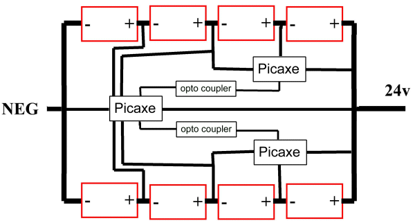
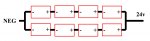
I have 2 solar battery banks that consist of (1) 8 x 6v batteries in series/parallel totaling 24v and (2) 12 x 2v batteries in series/parallel totaling 12v

24v-Battery-bank.jpg


I would like to monitor the voltage each battery independently

The power supply to the Picaxe chip will share the same negative as the battery banks

To measure the voltage of each battery accurately I think I need to access the Neg and Pos of each independently

I have thought of 2 possible ways but I am not really happy with either.

1. use the common Neg and read the +ve of each battery in sequence, starting from the NEG end and then subtracting the previous battery value to give the current battery value i.e bat1 = bat1, bat2 = bat2-bat1 etc. one issue is that the last 2 batteries will be seen as one.

2. Using many Picaxe 8M's as slaves with a totally separate power supply for each on each battery and then sending the result to a master picaxe chip.
I think this is expensive, cumbersome, not very elegant.

Being an electronic novice I don't really have a clue how to do this properly and would be grateful for a kick start.

Can anyone please offer me advice.

Cheers
Paul
 

premelec

Senior Member
Your diagram doesn't seem to reflect your actual described physical configuration - be clear how many voltages you wish to measure - e.g. per cell per string etc. This problem has become very popular in the context of electric autos with hundreds of cells and more... Specify how fast, how accurate and maximum voltage you need to shift down to PICAXE input levels. One way is simply using multiplexing relays which give electrical isolation... anyhow think more just what you need in accuracy and speed of reading - these are important parameters.... Nail down your specs and a solution will follow... [unless you are too darn picky :) ]
 

SAborn

Senior Member
You would likely need to use opto couplers or you will end up with ground loop problems.

Where are you located??
A friend of mine has done a cell monitor for his lithium iron cells used in a off grid system, but i dont recall how he done it but remember he had ground loop problems to solve.
 
Your diagram doesn't seem to reflect your actual described physical configuration - be clear how many voltages you wish to measure - e.g. per cell per string etc.
The diagram is only just an indication of a series/parallel system,

I'm only just at the starting stage of this project and it really will only be used for monitoring the general health of the individual batteries, not for any control/charging purposes.
The batteries (cells) I will be monitoring are 2v in the 12v bank and 6v in the 24v bank
Multiplexing relays sounds interesting, do you have a part suggestion?

The link kindly provided by "eclectic" had in it reference to the DC2438 1-wire smart battery monitor chip, this seems like a good place to start.
I have has success with using several DS18B20's so am a little familiar with the 1-wire system
Time to do some more study :)
cheers
P
 

Haku

Senior Member
It could be done with 3 Picaxes, a main one that connects the the battery bank negative which can read the total voltage and the 'bottom' 4 batteries voltages, and two that read the 'top' 4 batteries voltages and transmit the readings to the main Picaxe through optocouplers.

This is a basic block diagram of a setup that will allow you to monitor the voltage of every individual battery using 3 Picaxes:


techElder

Well-known member
You have to go further in your design than just monitoring the battery voltage. Why monitor it? Perhaps you want to adjust the charge for each cell?

Thinking further that way means that each cell will have to have some way to divert charge away from itself when the monitoring determines that needs to happen.

So, the design that I've seen has a PICAXE at every battery with a program to monitor and dump the charge current to a dummy load when the cell doesn't need it.
 

graynomad

Senior Member
Here's a design I did using an AVR chip, it allows unlimited numbers in a serial chain and does temp as well. It should also handle load dump situations up to 45v.

Untitled-1.jpg

It gets power from the monitored battery though so won't work with 2v batteries. I've been meaning to do a 2v version, might get onto that.
 
Last edited:

lewisg

Senior Member
QUOTE=scamanderriver;187718]1. use the common Neg and read the +ve of each battery in sequence, starting from the NEG end and then subtracting the previous battery value to give the current battery value i.e bat1 = bat1, bat2 = bat2-bat1 etc. one issue is that the last 2 batteries will be seen as one.[/QUOTE]

From your drawing if you had 8 ADC channels (18M2) you could measure each battery. Simply ground your board at the negative end of the bank and 1 ADC per battery. As you mentioned you will need to subtract the voltage of other batteries in the series between the ADC you are reading and ground. Your voltage dividers will be tricky. I've been using 300k 15 turn pots with good results for under 20V. BE SURE to read the comments below regarding over current protection (fuses).


2. Using many Picaxe 8M's as slaves with a totally separate power supply for each on each battery and then sending the result to a master picaxe chip.
I think this is expensive, cumbersome, not very elegant.
l
Using one chip per battery is elegant due to it's simplicity. As pointed out by graynomad since these are 6V batteries you already have a power supply for each of the PICAXE08M2 chips. Simply run the positive side through a 3.3 volt regulator to power the chip. You might even be able to get away with one of the little ones in a TO-92 (epoxy transistor style) case. Easy-peasy.

Since 08M2 are under $3 each it is a false economy to attempt complicated switching arrangements the could cause REAL problems in the high current EXPLOSIVE environment of a battery bank. For safety each positive wire going to a RICAXE board needs a fuse as close to the battery positive terminal as possible. These fuses need to be enclosed in a water (if not vapor) proof holder to prevent the possibility of igniting a hydrogen explosion. You can ignore hydrogen precautions if you are using completely sealed batteries like AGMs. However if you are using something like golf cart batteries (best bang for the buck) BE CAREFUL!

If you want a graphic demonstration of what can happen with small gauge wires around big batteries, using pliers, short a length of 14 AWG across the terminals sometime. If you choose to do this bit of destruction be sure the battery has been off a charger for at least an hour, have the battery outside away from combustible materials, wear safety gear (including goggles) and be sure to have a place to drop the wire when it goes incandescent the won't catch fire or cause damage.

At it's most basic each battery module will have:
*Inline fuse and holder.
*3.3V positive voltage regulator with one or two caps for filtering.
*PICAXE08M2 and associated 2 resistors and download header or jack.
*2 resistors for a voltage divider.
*Optocoupler and a resistor to communicate data to the master. This is the part that solves your common ground problem.

With careful shopping you should be able to do these boards for less than $10 each.

Good luck! Do you have any pix of your battery bank? I may want to fiddle with this for marine house battery banks...
 

lewisg

Senior Member
1. use the common Neg and read the +ve of each battery in sequence, starting from the NEG end and then subtracting the previous battery value to give the current battery value i.e bat1 = bat1, bat2 = bat2-bat1 etc. one issue is that the last 2 batteries will be seen as one.
From your drawing if you had 8 ADC channels (18M2) you could measure each battery. Simply ground your board at the negative end of the bank and 1 ADC per battery. As you mentioned you will need to subtract the voltage of other batteries in the series between the ADC you are reading and ground. Your voltage dividers will be tricky. I've been using 300k 15 turn pots with good results for under 20V. BE SURE to read the comments below regarding over current protection (fuses).


2. Using many Picaxe 8M's as slaves with a totally separate power supply for each on each battery and then sending the result to a master picaxe chip.
I think this is expensive, cumbersome, not very elegant.
l
Using one chip per battery is elegant due to it's simplicity. As pointed out by graynomad since these are 6V batteries you already have a power supply for each of the PICAXE08M2 chips. Simply run the positive side through a 3.3 volt regulator to power the chip. You might even be able to get away with one of the little ones in a TO-92 (epoxy transistor style) case. Easy-peasy.

Since 08M2 are under $3 each it is a false economy to attempt complicated switching arrangements the could cause REAL problems in the high current EXPLOSIVE environment of a battery bank. For safety each positive wire going to a RICAXE board needs a fuse as close to the battery positive terminal as possible. These fuses need to be enclosed in a water (if not vapor) proof holder to prevent the possibility of igniting a hydrogen explosion. You can ignore hydrogen precautions if you are using completely sealed batteries like AGMs. However if you are using something like golf cart batteries (best bang for the buck) BE CAREFUL!

If you want a graphic demonstration of what can happen with small gauge wires around big batteries, using pliers, short a length of 14 AWG across the terminals sometime. If you choose to do this bit of destruction be sure the battery has been off a charger for at least an hour, have the battery outside away from combustible materials, wear safety gear (including goggles) and be sure to have a place to drop the wire when it goes incandescent the won't catch fire or cause damage.

At it's most basic each battery module will have:
*Inline fuse and holder.
*3.3V positive voltage regulator with one or two caps for filtering.
*PICAXE08M2 and associated 2 resistors and download header or jack.
*2 resistors for a voltage divider.
*Optocoupler and a resistor to communicate data to the master. This is the part that solves your common ground problem.

With careful shopping you should be able to do these boards for less than $10 each.

Good luck! Do you have any pix of your battery bank? I may want to fiddle with this for marine house battery banks...
 

techElder

Well-known member
Another reason to monitor your cell voltages (on certain battery types) and communicate that information is cell inversion; a below-zero voltage condition.

Detect this condition before it happens, recharge correctly and you can keep a mediocre battery from failing.
 

techElder

Well-known member
If you are going to monitor cell voltages, another piece of data that would eventually be important to record is time.
 

techElder

Well-known member

Attachments

Last edited:

westaust55

Moderator
Another option is to use an X1 or X2 PICAXE chip and a DS2438 1-Wire smart battery monitor chip.
All of the DS2438's can be wired to a single PICAXE input and then use the 1-Wire commands. (The 1-Wire is only available on X1 and X2 parts).

The DS2438 has on cip temperature and can also monitor voltage and current for the/each cell.

Datasheet for the DS2438 is here:http://datasheets.maxim-ic.com/en/ds/DS2438.pdf
 
Thanks guys for all the input, lots of ideas,

I'm leaning towards using the DS2438, even though my intention is only to monitor for general battery health is would be nice to play with the data the DS2438 can collect. I'm wondering if anyone used one before?

I'm happy now the project seems do-able at my skill level. :)
I do love playing with these Picaxe chips

Thanks, I really appreciate it.
P
 
Thanks Lewsig for the reminder of safety issues dealing with battery banks,
they may be low voltage but hell they can cause a bang when short circuited, very dangerous !!
I will definitely take precautions.
 

premelec

Senior Member
Just to bring it back to simplicity - A DPST [or DPDT if you like] relay for each voltage to be monitored with about 1K ohm in series with each terminal JIC [Just In Case]. The relays can be had for about $1. each and can be latching or not have no ground loop problems and at the low voltages no particular problem. The PICAXE would control which relay to activate and the measuring circuit will float unless contacted by a relay - could have PICAXE battery charged by scanned voltages to keep it all alive or separate power... in any case have fun with all the possibilities. This suggested system is pretty slow - and the relays clicking can be either reassuring or annoying :)
 

westaust55

Moderator
I'm leaning towards using the DS2438, even though my intention is only to monitor for general battery health is would be nice to play with the data the DS2438 can collect. I'm wondering if anyone used one before?
P
I have a DS2438 chip but do not recall using it on my 1-wire network demo to date.

To consider this route I suggest:
1. Find a source of the chip - EBay may be cheapest
2. Read my 1-wire network info posted on this forum
3. Read this website on the DS2438 as well:http://www.societyofrobots.com/member_tutorials/node/101
 

graynomad

Senior Member
One thing I don't understand about using the DS2438 is how will you isolate the chip, the ones at the top of the bank will be sitting at 20-odd volts.

I've thought of using them and other similar chips in the past but they all seem to be designed for small batteries so the current sensing is not usable on a large battery bank. So you effectively have a temp sensor and an ADC, both of which can be done internally with a processor (admittedly not as accurately).
 

westaust55

Moderator
Valid point Graynomad.

Looking further the Linear Technology LTC6802-2 - Multicell Addressable Battery Stack Monitor
as mentioned by TexasClodHopper is a better chip for the ability to easily measure the voltage of up to 12 cells in sereis.


The DS2438 could potentially ( :) ) monitor the current through any cell independant of position in the string but would need some serious though (if at all possible) as to how to interface to measure the cell voltages when seeing the low side of the voltage sense circuit is in effect internally tied to the 0V pin so some form of isolation is required which may be difficult with a bi-directional 1-Wire bus. But then there are data/signal voltage level changing circuits for i2c bus circuit but now we are adding more components and it gets messy.

Shows how some other forums are:
Graynomad recently (mid Nov 2011) posted some information on another forum and prompted a day or so later for any feedback only to receive the comment:
"What's that, newb patience? Oy!"
Newb?- graynomad has around 3449 posts on that forum!. :eek:


:
 
Last edited:

graynomad

Senior Member
He he, that was on the Arduino forum, I spend a lot of time there :)

I think he was joking, the Arduino forum is known for being pretty friendly, maybe not quite as much as here because there are a couple of grumpy Arduino experts and I haven't noticed any grumpy Picaxe experts, but pretty good.

For a much harder time go to AVRfreaks, only for the strong willed :)
 
Last edited:
Top