jedynakiewicz
Senior Member
I intend switching some small DC motors (12v 300mA, brushed) using a TIP125 PNP transistor. I note that the internal circuit of the transistor (Figure 1) shows a protection diode across C-E. Would this be sufficient to deal with the inductive load back-EMF from the motor or do I need a flywheel protection diode across the motor as well?
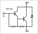
Figure 1
Similarly, I am switching inductive load using a logic-level MOSFET - STB55NF06L and this also has a diode shown in the schematic (Figure 2)- I understand that this is inherent within the substrate. Is this also sufficient to deal with back-EMF or do I also need back-EMF protection diodes across the inductive load?
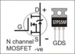
Figure 2
I would appreciate advice and guidance and perhaps some explanation of why these diodes are there within the semiconductors and how they may be employed - I can't seem to find any references on what they are all about in detail beyond being "protection diodes".
Figure 1
Similarly, I am switching inductive load using a logic-level MOSFET - STB55NF06L and this also has a diode shown in the schematic (Figure 2)- I understand that this is inherent within the substrate. Is this also sufficient to deal with back-EMF or do I also need back-EMF protection diodes across the inductive load?
Figure 2
I would appreciate advice and guidance and perhaps some explanation of why these diodes are there within the semiconductors and how they may be employed - I can't seem to find any references on what they are all about in detail beyond being "protection diodes".
Last edited: