Technoman
Senior Member
Hi,
We just got 14 AXE300 boards. We do believe in their great potential, educationally speaking, in interfacing with Grove modules.
In a previous thread https://picaxeforum.co.uk/threads/grove-lcd-rgb-display-problem.30780/#post-320236, hippy disclosed a partial circuit diagram of the AXE300 board.
Still, the link to the data sheet is inoperative (404).
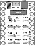
Would it be possible to get its full circuit diagram and more the layout (drawing)? Need them for making student's doc.
Two capacitors (1 small and 1 bigger) are next to the Grove connectors ; are they only there for a decoupling purpose?

