Hi,
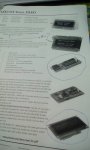
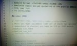
They pre-programmed its 18M2 with the program code linked from the "shop" page
HERE. The "default" text is just after line 50, which can be edited and downloaded via the
3.5mm Programming socket , if you wish to change the "boot up" text.
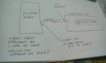
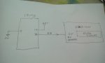
A problem is that the AXE133 can be used in several different ways, but the "normal" (and easiest) way is to send control codes and text from
any other PICaxe into its
Main header socket (H2). Note that the diagram does NOT say "pin marked B7" it says: "
OUTPUT for example (e.g.)
B (dot)
7" (i.e. a Port . Pin identifier). That should work with any PICaxe that has 18 or more pins, but would need to be changed for smaller PICaxes like the 08 and 14M2. IMHO the instructions are quite clear in saying:
"Main Header H2 (IN, V+,0V)
The main header provides connection for the power supply (4.5V or 5V DC on V+). The pin marked IN connects directly to the controlling PICAXE output pin. Do not connect via a Darlington driver buffered output on a project board - always connect directly to the PICAXE pin."
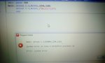
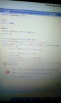
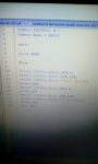
Typical program code for the "controlling PICaxe" is shown immediately below the diagram, or Neil has given a more complete version in post #4 above. Any "convenient" Output pin can be used that supports the SEROUT command, just configure the program accordingly.
Cheers, Alan.
")