AXE022 Board Connections

westaust55

Moderator
Hi all,
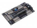
new to this forum havinging recently purchased a PIC040X1 and an AXE022 protoboard. :) I am seeking some assistance identifying the signals associated with each solder pad on the AXE022 proto board as the mask lettering on mine is very poor.
From the AXE022.pdf there are a total of 32 signals but there are 40 pads around 3 edges of the AXE022 board. :confused:
Possibly some erudite person could list the purpose (allocated signal) for each solder pad starting from the pad nearest the reset switch.
Thanks in anticipation.
 

westaust55

Moderator
AXE022 Protoboard Solder Pad Assignments

The AXE022 pdf datsheet allocates a label to each group of solder pads on the proto board but at least in my case the silk screening to label these has been poor and predominantly only the digit portion is visible. :mad:

I was hoping someone may have known or had a diagram but in the seeming absence of this having already been documented I have gone down the route suggested by InglewoodPete and done the work. :)

To make life easy in future for others, I attach a copy of what I have drawn up for myself. I have omitted the Serial I/O, resonator, EEPROM and power supply parts of the circuit as these are well enough documented in the AXE022 datasheet from Revolution Ed.
 

Attachments

Last edited:

domwild

Member
The AXE022 pdf datsheet allocates a label to each group of solder pads on the proto board but at least in my case the silk screening to label these has been poor and predominantly only the digit portion is visible. :mad:

I was hoping someone may have known or had a diagram but in the seeming absence of this having already been documented I have gone down the route suggested by InglewoodPete and done the work. :)

To make life easy in future for others, I attach a copy of what I have drawn up for myself. I have omitted the Serial I/O, resonator, EEPROM and power supply parts of the circuit as these are well enough documented in the AXE022 datasheet from Revolution Ed.
Inglewood and Westaus
Thanks for your help. Great diagram! The distances are 2.54mm or 1/10" if I want to place a terminal block there rather than solder wires in. The magnifying view shows the letters in a separate column to the numbers, so I was not the only customer complaining about missing letters/digits. Looks like they later fixed that up.

Looks like I have to buy myself a temperature controlled soldering station with a fine tip to work on this proto board or will this stingy pensioner get away without spending $100 by just buying a fine tip?? The Jaycar $40 one does not have a centigrade scale, which the $100 one has.
 

westaust55

Moderator
Top