I have two LM386 audio amplifiers being fed from an MP3 module. Everything is working well on the prototype apart from the switching arrangements. I have a 5v supply to the picaxe and a 9v supply for the LM386
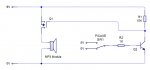
I need a picaxe to turn on the power supply to the amplifier so that it can be used as an alarm clock/player. I have tried the standard interface of a transistor on the ground connection and controlled through a resistor from the picaxe. This does not appear to work – when the transistor is turned off there is a loud continuous clicking from the speakers and I suspect that power is being grounded by all the other earth connections on the audio circuit and also pin 2 of the chip.
I therefore tried to switch the power side but that failed miserably – my knowledge of transistor function was extremely basic at that stage. I know a little more now (knowledge upgraded now to just very basic) and realise that such a proposal was doomed from the beginning.
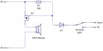
My latest attempts involve the use of a relay on the power supply side but this is not ideal as it clicks every time it operates (presumably from contact bounce) and I would prefer to have a silent action. I will also have problems fitting the relay in the limited space available in the enclosure.
I have tried to search the forum but have not found any search combination that comes up with anything meaninful so sorry if this has been discussed before. Can anyone offer any suggestions? Can a MOSFET be put on the supply side?? - I have never worked with a MOSFET before.
Thanks in anticipation
Eggie
I need a picaxe to turn on the power supply to the amplifier so that it can be used as an alarm clock/player. I have tried the standard interface of a transistor on the ground connection and controlled through a resistor from the picaxe. This does not appear to work – when the transistor is turned off there is a loud continuous clicking from the speakers and I suspect that power is being grounded by all the other earth connections on the audio circuit and also pin 2 of the chip.
I therefore tried to switch the power side but that failed miserably – my knowledge of transistor function was extremely basic at that stage. I know a little more now (knowledge upgraded now to just very basic) and realise that such a proposal was doomed from the beginning.
My latest attempts involve the use of a relay on the power supply side but this is not ideal as it clicks every time it operates (presumably from contact bounce) and I would prefer to have a silent action. I will also have problems fitting the relay in the limited space available in the enclosure.
I have tried to search the forum but have not found any search combination that comes up with anything meaninful so sorry if this has been discussed before. Can anyone offer any suggestions? Can a MOSFET be put on the supply side?? - I have never worked with a MOSFET before.
Thanks in anticipation
Eggie