ADXL335-3-Axis-Analog-Output-Accelerometer

Gramps

Senior Member
Lance Benson said to Gramps:

As it turned out, I received the non-i2c version of this the day before you posted:

Today I wired it up and scotch-taped it to a pencil. It works reliably reading the "Z" axis with this code:
Code:
' 08accel_xl335 ' accelerometer
#picaxe 08M2 ' 20M2
#terminal 4800

do
readadc10 C.1,w1 ' read "Z" axis of XL335 accelerometer
if w1 < 380 then ' acceleration towards a strike
sertxd(#w1," ")
pause 200 ' reduce/eliminate double reports
endif
pause 5
loop

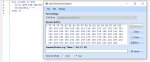
As we move the ADXL335-3, the numbers change in the terminal. The range is 270 to 370.
My question is how to code this sensor to a servo output so the servo would track the movement of the accelerometer?
Would you have to map the numbers of the accelerometer or is there a simple command?
 

lbenson

Senior Member
I don't exactly understand this question. What is the servo tracking--the maximum acceleration of the sensor in the down direction? This would seem unreproduceable with any consistancy.

However, if the theoretical task is to map values in the range of 270-370 (say in w0) to a range of 75 to 225 (say in b2), then you have
b2 =w0 - 270 * 150 / 100 + 75
Try this in the simulator:
Code:
for w0=270 to 370
  b2=w0-270*150/100+75
  sertxd(#b2," ")
next w0
xl335 to servo.jpg
 

Gramps

Senior Member
Lance, thanks so much for the clear explanation of how to match input and output.

What is the servo tracking
As I rolled the sensor, the numbers changed from low to high and back to low again.
My idea was to mount the sensor on my shoulder so that when I move left or right my robot arm would move left or right.
 

Buzby

Senior Member
Hi Gramps,

There is a thread about 3-axis accelerometer stuff here : https://picaxeforum.co.uk/threads/gy-521-mpu6050.31177/

I posted some screenshots and a video showing how the three axies correspond to 3-D orientation.

As you have already discovered, a single axis shows the same value at two different angles. To determine whether the device is tilted either 'left' or 'right' you need to include another axis and some maths. ( Or limit the motion to 90' with no movement in any 'off axis' direction, which I think will be difficult in a body-worn application. )

I found the 'serialplot' program to be very useful when determining just what is happening as the accelerometer is rotated around each axis.

The OP of the of original thread gave up and switched to A******, but if you are determined I'm sure you'll have it working on a PICAXE.

Cheers,

Buzby
 

Gramps

Senior Member
but if you are determined I'm sure you'll have it working on a PICAXE.
LOL!!! I'm ready to try the pot with the weight hanging on it! Whoever thought it could be that complicated!
Looking into a nunchuck
 

Buzby

Senior Member
As Lance says, it's easy to get the values from a nunchuck, but it won't be any easier to work with than your chip.

Remember, Lance also said in that post, "I don’t know what to do with an accelerometer, so I ignored those values. ".

The 3-axis accelerometer allows a device to 'know' which way it is pointing in a full 360' sphere, but it takes a heap of maths to work it out.

With just two axes, and a slightly smaller heap of maths, you can measure tilt alone.

Here is the maths, enjoy ! https://www.analog.com/media/en/technical-documentation/application-notes/AN-1057.pdf

Cheers,

Buzby
 

Eng460

Well-known member
Hi Gramps, a very interesting addition to your project. I am looking forward to following how it goes. But no simple command that I know of for your ultimate goal.

You have succeeded in the first step, communications with the device, which is a very good start.

Next step is to determine what those numbers mean. As Buzby says, it needs a heap of maths, but it’s not rocket science either. (The maths involved is the basis for rocket science, but its the basic high school maths they assume you already understand before you even enrol in rocket science 101.)

Do you have a data sheet which shows you how to calibrate or translate those numbers into meaningful numbers of metres/sec^2, or ft/sec^2 (depending on which you prefer)?

Acceleration is a vector quantity which simply means it requires a direction as well as a magnitude, and those three axis define the directions. Three axis are each at right angles so movement in any direction is independent of the other two.

Then remember that acceleration is defined as rate of change of velocity. All the maths formulas involve time. Hence you need a sufficiently accurate time, and that will be the first hurdle. Not an atomic clock, but a reasonably consistent time interval. Perhaps pauseus will be suitable. I am thinking you might need a separate board that does nothing but measure those three accelerations at a repeatable time interval, and just pass them to a different board to apply the maths, similar to what was needed to solve my issues in a recent thread involving timing issues and servo control.

Then the maths. It will be a challenge with the basic integer maths of the M2 Picaxe chips, but the X1 and X2 chips have unwary maths functions which may do at a pinch, as I expect that two significant figure accuracy might be enough. Otherwise you will have to explore using that floating point maths processor which is listed in the data sheets. So it is worth downloading all the resources for that device, as that may be more practical that muddling through with Unary maths.

And it will still only give integer outputs so mm might be a suitable dimension to use without requiring fractions.

I may be starting too simple, or may have already lost you, So before I bore everyone totally with an unwanted or unneeded physics lesson, it would help if you let us know where you are up to in understanding this stuff, or if this approach is interesting to you.

Alternatively, someone else may have a totally different approach, even using sensors which use a totally different principle. It may take a little exploration on several approaches to identify which will work best for you.

Eng460
 

Eng460

Well-known member
Hi Gramps, I’m sorry, that was my intention at all. I have been looking at those sensors and trying to think of an application, so was keen to see how you go. But it would be a challenge, given the Picaxe maths limitations, and you may have come to the right conclusion anyway.

I have been looking at those sensors for a while, and wondering what I could do with them. But I am not very interested in doing something “just ‘cos it would be cool”. I need a practical application to motivate me to follow it through. It does look like all the needed information is listed including the always excellent West Australian’s tutorials to make it practical.

The sensor, perhaps even the six axis, so it includes the three rotation axes, and the maths coprocessor and fun maths, all in one project! Hmmmm. It’s certainly tempting. Definitely on the list for one day.

For your project however, it may in the end be more practical to work on appropriate position sensors, and perhaps movement detect linear movements by linear potentiometers and rotation and joints by ordinary potentiometers. Calculating movements from accelerations may be just a step too far, especially without those rotation axes.

Eng460
 

Buzby

Senior Member
Another 'off the wall' idea ....

All modern smartphones have a fully-fledged 3-axis gizmo with all the trimmings.

Strap one to your shoulder, and just Bluetooth the readings to your robot.

There's probably an app for that.

Cheers,

Buzby
 

Gramps

Senior Member
But it would be a challenge, given the Picaxe maths limitations
More so MY math limitations LOL
Sometime ago years ago we salvaged some pots with recoil strings off of something we don't even remember what to use for this project.
Just thought it would be easier and very cool to have one sensor mounted on our shoulder that would detect both directions up and down and left and right.

Strap one to your shoulder, and just Bluetooth the readings to your robot.
There's probably an app for that.
Buzby, you guys never cease to amaze me with cool ideas! Please start a thread on how to do this LOL
 

Gramps

Senior Member
This sensor might give some useable data.

HMC5883L Triple Axis Compass Magnetometer Sensor Module
 
Top