adjustable duty pulse strecher

newbe

New Member
I need help with this its for a diesel parking heater to run on vegtable oil it is to thick to pump at the heaters 20 percent duty cycle pulse . I need code to make 0m8 stretch the pump pulse to 40 percent duty or adjustable with pot the pump rate vary s 1 to 6 a second
 
Last edited:

hippy

Technical Support
Staff member
It sounds like something a PICAXE would be suitable for but details on the actual output you have, the output you need, would help identify the best way to do it.

For example, is the 20% duty cycle 2 ms on in every 10ms, or 2 seconds on in every 10 ? Does the duty cycle or pulse rate vary ?
 

newbe

New Member
The output of pump wires 12 volt pulse from 2 to 7 pulses per second maintaining 20 percent duty cycle .I need pic to follow pump pulse rate at 40 percent duty. I have aliexpress PWM with adjustable duty cycle its duty cycle stays at set rate when increasing pulse rate but no way of it following the fluctuations in pump speed from heater controller
 

PhilHornby

Senior Member
I'll have a stab :unsure:

Assuming waveform A is the current signal that drives your pump ...

In this example (@7Hz), it comprises a 28mS pulse (followed by 4 x 28mS low). So it is HIGH for 1/5th (20%) of the period and LOW for 4/5th (80%).
(Ignore any rounding errors!)

You want to transform it to waveform B ?

If you can live with the output being out of phase with the input, I have some code that generates waveform C (untested).

25213

Rich (BB code):
#picaxe 08m2
#no_data

symbol SignalDetect = C.1                 ;input signal
symbol NewSignal    = C.2                 ;new output signal

symbol PulseLen = W2                      ;somewhere to store input pulse length

      output NewSignal                    ;declare this pin an o/p. (sets it LOW)

Do
      pulsin SignalDetect,1,PulseLen      ;Measure length of time signal is HIGH
                                          ;at this point, the input pulse has ended.
      
      if PulseLen > 0 and PulseLen < 32768 then ; if zero, no pulse in 655mS. 
                                          ;if >= 32768, it's too big for us to double-it.
            PulseLen = PulseLen * 2       ;otherwise double its length (to change 20% to 40%)
            pulsout NewSignal,PulseLen    ;and set our o/p HIGH for that length of time
                                          ;The output will stay LOW, until the END of
                                          ;the next input pulse.
      endif
loop
EDIT: [tweaked a couple of lines of code, in light of later comments in the thread]
 
Last edited:

PhilHornby

Senior Member
As it stands, this will only work down to ~3Hz ) 0.61Hz (before the PulseLen = 2 * PulseLen generates a value that won't fit in 16bits and it 'wraps around') [assuming a 20% duty cycle].

so if PulseLen > 0 and PulseLen < 32768 then would probably [still] be in order!​

Lowering the frequency to 2 or 1MHz with setfreq would probably be a way to fix it- but I leave it as an exercise for the OP ;)

Counting the 'number of times' around a loop, as a means of measuring the input pulse length could be used to keep the o/p in phase with the input, as there would be no need to wait for it to end, before starting ours...

EDIT: Corrected my maths :)
 
Last edited:

AllyCat

Senior Member
Hi,
PulseLen = 2 * PulseLen ; .. double its length (to change 20% to 40%)
I must admit that I "overthought" this problem and simply waiting for a pulse, reading its length, doubling the value and Outputting a pulse is indeed the "obvious" solution. But Phil is rather pessimistic, PULSIN and PULSOUT can handle up to 655.35 ms (@ 4 MHz), which meets the 20% to 40% conversion at the minimum 1 Hz frequency requested.

It will "fail" if the input duty cycle is greater than 33%, because the output pulse won't finish in time, so a "trap" (e.g. using MAX) on the input/output values would be wise. For longer periods, SETFREQ m2 should be fine, but caution at 1 MHz and below may be needed, because of the PIC's "Watchdog Timer" (~ 2.2 seconds) causing an unexpected reset.

Not really relevant here, but note that: PulseLen = PulseLen * 2 is faster (and might use slightly less program memory), and PulseLen = PulsLen + PulseLen is faster still (since addition is faster than multiplication), than the above (when multiplying by 2).

Cheers, Alan.
 

PhilHornby

Senior Member
You're probably aware anyway, but ...

The output Pin (C.2) will be High impedance for a milli-Sec or two, when the Picaxe boots. If it's driving a MosFET, that may get a 'kick' of full-power. I've no idea how that would affect a "diesel parking heater" - mainly because I have little idea, as to what a "diesel parking heater" is :) .

Ditto, the input Pin (C.1) should be pulled low - but since it is being fed from a 12V source, it will have to be fed from a potential divider, to keep the voltage seen by the Picaxe, down to 5V.
 
Last edited:

hippy

Technical Support
Staff member
To double the duty I would simply replicate the input pulse as an output pulse, but keep it going for twice as long as it was present for. Something like -
Code:
MainLoop:
    Do
        Do
        Loop while INPUT_PIN = 0
        High OUTPUT_PIN
        w0 = 0
        Do
          w0 = w0 + 1
        Loop while INPUT_PIN = 1
  
        Do
           w0 = w0 - 1
        Loop While w0 > 0
        Low OUTPUT_PIN
    Loop
 

newbe

New Member
I tried both codes not seem to work yet for me It could be other problems on my end .I havent done alot of electronics lately .For now I will use a heated fuel system .I fuel my truck and heat 2 homes on free vegtable oil The heating systems I have made are large heavy expensive .I have manage to get the Chinese diesel parking heater to work very well on vegtable oil it seems no one else has it took a lot of time .Thank you very much for your help .I will get back to this duty cycle problem later
 

AllyCat

Senior Member
Hi,

The two programs are quite "simple" so (assuming the PICaxe Program is being Downloaded correctly), then it's probably a "Hardware" issue. It might be either in the initial specification/description or the actual Hardware design or implementation. My guess would be an error in the handling of the current or voltage required by the "heater pump".

However, the program is easy to test: First put a #TERMINAL 4800 line near the top of the program (to start the PICaxe Editotor's "Terminal Emulator" window). Then, I would add a line SERTXD("I") immediately after the "PULSIN..." (or "HIGH ..") command line, and/or a line SERTXD("O") immediately after the "PULSOUT..." (or "LOW ..") command line:

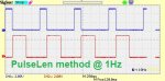
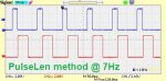
That should send an "I" each time a pulse is received and/or a "O" each time a pulse is transmitted, so a string of "IOIOUO...." should continuously build up in the Terminal Window. It of course requires pulses to be input to the C.1 or Hippy's INPUT_PIN . If that works, then the SERTXD commands could be modified to report the actual pulse widths (e.g. SERTXD(" ",#PulseLen) , or after hippy's middle Do.. WHILE line) for an easy "sanity test".

Cheers, Alan.
 
Top