late_voyager
New Member
late_voyager,
I thought of my next test.
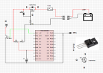
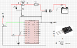
Disconnect the 10v from the voltage divider.
Measure the voltage at the pin. It should be 0v.
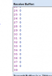
Run the program to find out what the raw ADC value reported by SerTxd( #w0, CR, LF ) is. It should be 0.
yes value is zero...
")