Hi,
Perhaps the best starting point is "Don't believe
anything you read on the Internet".
")
Decide which sources you find are "usually reliable" but still use a critical eye. Generally the PICaxe Manuals are very good for their intended audience but sometimes they can be "misleading", perhaps due to an oversimplification. Also there have been many different PICaxe chips developed and they might not all behave in exactly the same way. Finally the manuals have probably been written mainly by a single person (they usually are ! ) and it's amazing how one can write something "incorrect" and then "proof read" it numerous times without noticing the error (been there, got the Tee Shirt).
As far as Microchip (and most other manufacturers) are concerned, their Data Sheets are trying to "protect their backs". It can be extremely embarrassing to have a product coming off a production line every few minutes (or even seconds!) with every one failing Final Test because of a specification error. So some of the parameters in the Data Sheets are incredibly pessimistic (for example the "Watchdog Timer period" which is used for the PICaxe NAP/SLEEP commands).
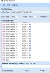
On the subject of the READADC/FVRSETUP interaction, I was fairly sure that I had written code snippets which use a "tight" READADC loop (to average the value). But in my search came across
this thread. where the code looks remarkably similar to that used by the OP.
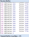
But, back to the original topic: The OP has implied that the ADC is reading a 1.8 volt level as a value of 40 (of 1024) which is almost "impossible" (because the reference voltage would need to be almost 50 volts, and "release the magic smoke"). So we need to discover what "implied" detail is incorrect ; it might be related to hardware, software, understanding or (our) assumptions. We can't do it by "remote control" so can only offer a list of possiblities in the "most probable" (and/or easiest) sequence. My brief list is:
- The divider chain is not connected to the (correct) PICaxe pin (Hardware). = Easy to check with a multimeter probing between the resitors' junction and the PICaxe
pin (NOT the socket or PCB). A "floating" input would also explain the large variations reported in #1.
- Software - Is the code listing EXACTLY (and all) that has been loaded into the PICaxe? Is the reported "w0" actually what is being written to the LCD?
- The PICaxe might be damaged = I put this last because it is
very unusual. But sometimes OPs do later admit that they had previously connected an excessively High or Reversed voltage, or shorted some pins together, etc..
Finally, a "lost" final digit (i.e. w0 = 40x) doesn't fully explain the observations because the value should be 700+. However, if the ADC input is 1.8 volts AND the FVR is not enabled, then we can predict that the Supply Voltage (Vcc = ADC reference) should be about 1.8 * 1024 / 40x = 4.5 volts, which is
very plausible.
Cheers, Alan.