ADC input impedance and capacitors.

dillond666

New Member
Hi,
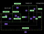
I am aware that there is a maximum input impedance that should not be exceeded when doing ADC (2.5k?) But wish to measure the voltage of a 12v battery using ADC10.
Could I use higher resistances in my voltage divider if I put a capacitor across the resistor that the Picaxe is measuring the voltage across? Would this capacitor lower the
impedance at the Picaxe input?
Any advice gratefully received.

Derek
 

dillond666

New Member
A capacitor is not required for DC inputs to the AD channel.
I realise it isn't required per se. I was hoping to minimise current drain on my 12v battery by using high value resistors
in the voltage divider. As I understand it, the Picaxe needs a certain amount of current flowing through the divider in order to charge the
internal capacitance in the Picaxe ADC and maintain accuracy, therefore I proposed to place a relatively much larger capacitor from GND to the ADC pin on the
Picaxe in the hope of reducing the impedance of the voltage source I'm trying to measure. I just wonder if my thinking is sensible or not

Derek
 

AllyCat

Senior Member
Hi Derek,

I don't think you've said which PICaxe you're using, but I've just taken a look at the PIC data sheet for the PIC16(L)F1825/1829 (PICaxe 14/20M2).

On page 371 it says:

"AD08 ZAIN Recommended Impedance of Analog Voltage Source = 10 kohms [max] - Can go higher if external 0.01uF capacitor is present on input pin".

They don't say how much higher, but even using 10k won't take much current from your battery. For convenience I'd probably use a 10:1 divider, i.e 10k across the A/D input to ground and "90k" (e.g. 91k or perhaps 100k and 1M in parallel) up to the battery. If you do use a capacitor, don't use an electrolytic which might leak current rather than improve the accuracy.

But IMHO the "reference" voltage that you use is likely to be more important in getting anywhere near using that 10-bit resolution effectively (of course there is a difference between "resolution" and "absolute accuracy"). If you're using the supply rail, the capacitor on the supply rail is probably more significant than that on the analogue input. I presume you'd be using a high quality supply regulator? Alternatively you could use the 2.048 volt FVR reference, or calibrate against the internal "1 volt" reference, but these only have an absolute accuracy of around 7%. However, whatever components and configuration you use you'd probably want to calibrate it against a decent voltmeter/multimeter at some time.

Cheers, Alan.
 
Last edited:

Dippy

Moderator
Wise words, and as you say, there are minimum recomendations by Microchip.
But always check the small print as these values vary with the ADC acquisition times.
Mr Thev can be helpful.

But yes, you can add a cap with a higher pot-div network up to a certain point.
It's not ideal esp. if you are doing fast repetitive ADCing and for reasons mentioned above.

A better solution is to switch the lower resistance network with something like a MOSFET.
So, you would switch it on , sample and then switch it off.
Then you'll be down at picoAmps for most of the time.
I've never tried using 2 I/Os (1 switch and 1 ADC) to achieve the same thing.
If you have the space maybe a very high impedance network buffered with a microamp opamp.
I daresay there are many slick solutions.

It's time to dig out your breadboard and have a bash and check for any funnies.
And try a simple pot-div and change the values until it starts going daft.
It'll be useful info for the rest of us too.
After that you'll have to experiment with micropower PICAXE settings!


Go to bed Martin, you Missus will think you're out clubbing again :)
 

srnet

Senior Member
I too had wories about the RC network drawing to much current from the battery.

I settled on a resistor divider of 200K and 22K, this is higher impedance than the spec sheets calls for, but it gives acceptable results for what is really a static measurement of the battery voltage. 200k and 22K give an output which is 0.099% of the battery voltage, so a close approximation to 1/10th.

Bear in mind that if the AD pin is connected to a high voltage via the resistor then there will be current flow due to the clamp diode on the PIC input pin, even when you disconnect the low end of the resistor divider. If you used a 200K resistor, then as the AD pin end will be at approx 5.6volts (as the clamp diode will conduct) there will be approx 3uA flowing in the resistor, from the battery.
 

MFB

Senior Member
If you need to use high resistor values to reduce battery drain the ADC input could be buffered by a rail-rail opamp, configured for non-inverting unity gain. Would also provide another level of PICAXE protection.
 

AllyCat

Senior Member
Hi,

For me, the fundamental question is what type is this 12 volt battery that needs "protecting" from such a small current drain? And where is the current to power the PICaxe (and any analogue buffering you might add) coming from? A car battery (or almost any rechargeable technology) will leak more current internally than that, and most cars will drain far more for the alarm system or central locking wireless receiver, etc..

If it's a small battery (Carbon or Alkaline, etc.) then testing with a very low current can actually be a bad idea. Near "end of life" they can still deliver close to the nominal voltage, but just keel over if you try to draw any significant current. That's why smoke alarms draw a gulp of current (flashing a LED) when measuring the battery voltage. The last thing you want is the battery to die when you try to sound the alarm.

So personally, I like Dippy's idea to switch the divider chain (and maybe power down the PICaxe). The only difference is I'd just use a complementary pair of bipolar transistors (e.g. BC548 + BC558) and one resitor to switch the divider chain at the top end (details on request).

Cheers, Alan.
 

srnet

Senior Member
If it's a small battery (Carbon or Alkaline, etc.) then testing with a very low current can actually be a bad idea
Sure, but then even a lower resistance divider chain still represents a 'very low current drain' for most batteries. So you either have to introduce an artifical load or do the obvious and measure the volts when the circuit is doing something.
 

hippy

Technical Support
Staff member
I'm prepared to be corrected but I've always read the maximum source impedance to be "for the ADC to meet its specified accuracy", that a higher impedance won't damage anything but may reduce accuracy, and at some point won't give useful results.

When the ADC executes, the Sample & Hold capacitor is briefly connected to the pin, and it charges at a rate depending on the source impedance; if impedance is too high it won't charge fully so when the C charge is converted to digital it will represent less that the source voltage is.

Adding an external C gets that pre-charged, so when sampled the S&H C quickly comes to the same.

Other tricks can include repeatedly performing an READADC on the same pin which brings the S&H C closer to what it would be if the sampling period were longer.

Even if the S&H C hasn't charged fully, as long as the source impedance isn't too high, it can return a usable ADC result, though converting that to an accurate representation of the source voltage may become harder.
 

dillond666

New Member
Thanks to everyone who has commented, It's been thought provoking.
The battery being monitored is a 160aH, one of a series string of 13 in an electric car (1 monitor circuit per battery). It's a fair point that the current draw of the divider isn't going to drain the battery but as I'm doing a new design I thought I'd go low power where possible. The point about absolute accuracy is a good one too, I didn't realise the internal 1v reference was not bang on. I may end up with a trimmer pot and calibrate to a good multimeter, I shunned the pot before because I was worried about vibration in the automotive environment.
The biggest problem I've had so far is that the Picaxe (08m) gets it's supply from the battery being monitored through a rather low tech 78l05 (I'll review that). The traction motor PWM controller switches at 15.7kHz, so it's like the picaxe sharing a supply with the biggest meanest servo on earth (not good). Maybe there is a better way to read my voltages accurately but I'm not sure. I'll be using Picaxe 08m2 for the next build. I had hoped that using a capacitor at the ADC pin to ground would have also formed a low pass filter which would be helpful.
I shyed away from op amp voltage followers too as I wanted minimum component count and wasn't sure if this would add another potential inaccuracy. It's funny how the harder you think, the more potential (imagined?) problems you come up with ;-)

Derek
 

nick12ab

Senior Member
It's a fair point that the current draw of the divider isn't going to drain the battery but as I'm doing a new design I thought I'd go low power where possible... I may end up with a trimmer pot and calibrate to a good multimeter, I shunned the pot before because I was worried about vibration in the automotive environment.
The biggest problem I've had so far is that the Picaxe (08m) gets it's supply from the battery being monitored through a rather low tech 78l05 (I'll review that).
You can use glue to stop the trimmer pot from moving if it will never need adjustment. You should also get a switching regulator - a 7805 is terribly inefficient.
 

AllyCat

Senior Member
Hi Derek,

You're using a PICaxe which can do division (like a Pot does)! But multiplication by a factor close to 256 might be better. You need to be careful with the scaling to avoid a 16-bit overflow but should be able to adjust to a fraction of 1%. Just hard code the calibration into the Program, or do something more sophisticated with the serial port or whatever User Interface you have.

I'd be perfectly happy with a 78L05 if it's just to run the PICaxe; I'm all for KISS (Keep It SimpleS).

Cheers, Alan.
 

Dippy

Moderator
"When the ADC executes, the Sample & Hold capacitor is briefly connected to the pin, and it charges at a rate depending on the source impedance; if impedance is too high it won't charge fully so when the C charge is converted to digital it will represent less that the source voltage is."
- exactly my point when I referred to Data Sheet impedance specs and acquisition time.

"Other tricks can include repeatedly performing an READADC on the same pin which brings the S&H C closer to what it would be if the sampling period were longer."
- you sure?
 

Reloadron

Senior Member
Given a choice and knowing the application I would go with a simple voltage divider of 3:1 making the full scale input 15 volts. 15 volts in gives you 5 volts out. I would absolutely add a trim pot. I would maybe place a 1K resistor in series with a 10K ten turn trim pot feeding a 5K resistor across the PIC input. Initially I would set up the divider network sans the PIC. Apply a known 12 volts and adjust the trimmer for 4 volts out. I guess if you want to get into a protection mode you could parallel the 5K resistor with a 5.1 volt zener diode like a 1N4733A. Nice touch but not really necessary. For locking the pot once calibration is done? Yes, a drop of glue or if you have a woman in your life nail polish.

As to power? There are no shortage of highly accurate DC/DC converters out there. For example the ZUS1R51205 DC to DC converter handles an input voltage range of 9 to 18 volts with a 300 mA output. More than adequate for driving a simple PIC application. If you want more current there are no shortage of units out there. The unit I used as an example cost about $18.00 USD. Good line regulation also. Remember how important the power for your PIC is as to the internal reference for A/D.

Me? Given a choice I buy several cheap LM7805 regulators and pick the best in the lot as close to 5 volts out and call it a day. :) I have used countless LM7805 regulators in low current automotive applications and never had a problem. The 5 volts just becomes a matter of what you want to spend and how accurate you want the end result to be.

Just My Take
Ron
 

mrburnette

Senior Member
I'm prepared to be corrected but I've always read the maximum source impedance to be "for the ADC to meet its specified accuracy", that a higher impedance won't damage anything but may reduce accuracy, and at some point won't give useful results.
<...>
Real test results on an 08M2

100K pot across +5V rail to Ground. Wiper set about 40% up from Ground (40K / 60K): wiper tied to PICAXE AD Pin#3 / ADC4. Program loop does a ReadADC10 on channel 4 into a word variable, next line sends the value and a string header to LCD at 9600 BAUD, and loop repeats.

Using the wiper through a 1K resistor to Pin#3 and a 0.01 capacitor to ground, a normalized reading was taken. Without the capacitor, the same reading was measured. Without the 1K resistor, the same reading was measured.

Now... noting that no changes were created in the value of the word target variable for the ReadADC10 command, I began putting in increasing resistor values between the wiper and the ADC channel on Pin#3 (no capacitor). I used the following: 100K, 340K, 750K with no change in the LCD display (read this as no change in the value of the word variable.) At 1M Ohm, the display would twiddle between the original value and one value lower... putting the capacitor back into the circuit, the display went to 0 and then slowly went back to the original value and was stable.

I interpret these results as indicating that for 08M2 silicon, the AD channel does not (generally) require a capacitor for DC measurements when the +5V PICAXE source is used as a reference voltage & without that capacitor, relatively high resistances feeding the AD pin directly will produce acceptable results. Obviously, changing to an external reference voltage will affect the test results.

- Ray
 
Last edited:

hippy

Technical Support
Staff member
"Other tricks can include repeatedly performing an READADC on the same pin which brings the S&H C closer to what it would be if the sampling period were longer."
- you sure?
It seemed to though I hadn't tested it fully nor specifically.

It's based upon the observation that if one READADC's a voltage and then floating ADC channels one sees the voltage decay, so after the initial sample is taken it doesn't leak away immediately. As long as the charge when sampling exceeds the decay rate, additional sampling of the same ADC should see the charge climb toward its correct level; effectively it's just extending the sampling time. At least that's the theory.

And it seems to be the case with the code below, a 20M2, B.0 connected to 0V, B.1 connected to midway of a 330K/330K; reads 93 with just a single READADC, 117 with two, 120 with three and 121 with four, so approaching the expected 127 but won't go above 121 unless the speed is dropped lower, increasing the sample time.

At 4MHz, even a single reading returned 127, which reflects my experience that high(ish) input impedance often doesn't have the impact that the Microchip datasheets may lead one to expect. For the 20M2 that's a recommended 10K maximum.

Code:
#Picaxe 20M2
#Terminal 4800

Do

  ReadAdc B.0, b1 ; 0V
  SetFreq M32
  ReadAdc B.1, b1 ; 330K / 330K
  SetFreq M4

  ReadAdc B.0, b2 ; 0V
  SetFreq M32
  ReadAdc B.1, b2 ; 330K / 330K
  ReadAdc B.1, b2 ; 330K / 330K
  SetFreq M4

  ReadAdc B.0, b3 ; 0V
  SetFreq M32
  ReadAdc B.1, b3 ; 330K / 330K
  ReadAdc B.1, b3 ; 330K / 330K
  ReadAdc B.1, b3 ; 330K / 330K
  SetFreq M4

  ReadAdc B.0, b4 ; 0V
  SetFreq M32
  ReadAdc B.1, b4 ; 330K / 330K
  ReadAdc B.1, b4 ; 330K / 330K
  ReadAdc B.1, b4 ; 330K / 330K
  ReadAdc B.1, b4 ; 330K / 330K
  SetFreq M4

  SerTxd( #b1, 9, #b2, 9, #b3, 9, #b4, CR, LF )

Loop
 

Jeremy Harris

Senior Member
If you're doing battery cell monitoring, on a battery with a cell capacity of 160 Ah, then there's no merit in getting the sense circuit current massively below the cell self-discharge current. I've built a couple of battery monitor systems, at the cell level, for both LiFePO4 and LiCoO2 cells, and generally they have a self-discharge current of around 0.0001C or so. My 80 Ah electric boat LiFePO4 pack discharges by around 50% if stored for 8 months, which is pretty typical for this chemistry, and indicates a self-discharge current of around 7 mA, or 0.000088 C, pretty close to the spec 0.0001 C.

If your battery pack has a similar self-discharge rate, then if you reduced the sense circuit current to, say 1/10th of the self-discharge current (say 1.6 mA for a 160 Ah pack), then the effect of the sense circuit on battery storage life would be negligible. 1.6 mA is a lot of current for a sense circuit. If the circuit used the 10 k maximum source resistance that Microchip recommend, then for full scale at the ADC the current would only be 500 µA, which would have no detectable impact on battery life at all.
 

womai

Senior Member
As already pointed out, 10 kOhm (not 2.5k) is the maximum value typically recommended by Microchip. Of course that number has a good amount of margin built in, so things aren't going to fall apart if you use e.g. 15 kOhm instead.

One more thing, the effective source impedance of a voltage divider is the two resistance legs IN PARALLEL. So if you have a 20 kOhm potentiometer set to midpoint the source impedance is actually only 10 kOhm, and this is your worst case for this potentiometer. If it is set to 2 kOhm or 18 kOhm then the impedance is just

R_par = (2 * 18) / (2 + 18) = 1.8 kOhm

A capacitor C in parallel to the input will - in combination with the voltage divider - create a low-pass filter (time constant R_par * C). This will stabilize the voltage at the ADC input (so you can't see fast changes but also won't be affected by high frequency noise), and will also buffer any shoot-through fro the ADC itself.

Wolfgang
 

hippy

Technical Support
Staff member
With the earlier code, going up to a 2M7 / 2M7 divider the results dropped to 63, 95, 105, 110 so the impact of increased impedance can be seen. Adding more consecutive READADC's didn't get the reading up beyond 110 apart from occasionally, so there is a limit to what can be achieved, but 110 is far closer to expected than 65 is.

At 4MHz, the results were 96, 120, 122, 122, so no gain after three consecutive readings. If one drops to 2MHz one can get a reading of 126 after just two consecutive readings. Up to 127 with two readings at 1MHz. A single reading seems to suffice at 500kHz.

So there's another alternative for extreme source impedances; drop operating speed.
 

boriz

Senior Member
Useful information chaps. Thanks.

Perhaps someone could edit this down a bit an put it on a tips-n-tricks or FAQ page?
 

AllyCat

Senior Member
So if you have a 20 kOhm potentiometer set to midpoint the source impedance is actually only 10 kOhm,
Hi,

I'm sure it was just a slip of the finger, it's actually 5k ohms (10k in parallel with 10k).

I guess that was the root of Dippy's cryptic comment in #6 "Mr Thev can be helpful." = Thevenin's Theorem - IMHO probably the second most useful formula for DC calculations (after Ohms Law).

Cheers, Alan.
 

fernando_g

Senior Member
As to power? There are no shortage of highly accurate DC/DC converters out there. For example the ZUS1R51205 DC to DC converter handles an input voltage range of 9 to 18 volts with a 300 mA output. More than adequate for driving a simple PIC application. If you want more current there are no shortage of units out there. The unit I used as an example cost about $18.00 USD. Good line regulation also. Remember how important the power for your PIC is as to the internal reference for A/D.
Good suggestion!
The product you suggest provides the input to output isolation, which I believe is an excellent idea whenever one is driving a high power load via PWM.
The voltage spikes generated by the wiring's resistance/inductance can cause ground loops or spikes that at best provide erroneous readings, at worst create a failure.
 
If you have got processor time to spare you might get get quite high accuracy and resolution by putting a small capacitor accreoss the input. then firstly doing an Low on the input to disccharge it, then doing a series of readadc's on it where you will find it will gradually charge and the read voltage will rise exponentially. When you have got it close enough for the resultion you need, you might then try taking n samples and adding the result of each then taking an average. That will probably allow you to smooth out any ripple or noise fluctuations on the input. All this came thanks to many other past forum contributions on the topic thanks

That way you should get around the problem with your high impedence input.

You might find Alleycats great 31/15 bit division subroutine in code snippets mght help too
http://www.picaxeforum.co.uk/showthread.php?21494-A-Simple-quot-Double-Word-quot-Division-Subroutine-(maximum-31-bits-by-15-bits)
 

popchops

Well-known member
Quick question: does the Picaxe ADC consume current when it's not sampling? Is there any internal impedance/leakage?

I ask because I'm trying to simulate my whole relay circuit including voltage divider (to measure relay drive voltage). The Picaxe provides a route to ground even when my low-side drive opens the relay circuit, so my simulation indicates that current will instead flow through my 'ADC' to ground, within the Picaxe.

Is this a real consideration? I built a similar circuit, and I did not notice current leaking through the relay using ADC as sink.

Thanks! Pops!
 

AllyCat

Senior Member
Hi,

All PICaxe input pins (Digital or Analogue) may have a small input leakage current, but the data sheet specifies typically < 5 nA, and a maximum of 125 nA at 85 degrees C, or 1 uA at 125 degrees C. However, you can't do a "d.c." analysis for the ADC inputs because the ADC uses a "Sample and Hold" Input stage; an analogue switch closes for some microseconds and the internal capacitor may take a small "gulp" of current until it equals the external voltage. That's why the maximum source resistance (or source impedance if a capacitor is present) is recommended to be 10k, because any voltage drop across that (caused by the sampling current) represents an error in the measurement (i.e. a maximum of around 2 mV for 10-bit resolution).

However, the ADC will draw some current from the internal supply rail whilst it is active, which the data sheet appears to indicate is typically 280 uA. That's the reason that the ADC should be switched off if the overall power supply drain is critical. But generally, the quiescent current in any external voltage dividing network (and most voltage regulators) will be much higher than any ADC currents. There is of course only one ADC which uses an analogue multiplexer to select which input pin is actually measured.

Cheers, Alan.
 

AllyCat

Senior Member
Hi,

All (ADC) Input pins have internal "protection" diodes to the supply rail and ground, so the voltage cannot be more than ~ +/- 0.6 volt outside this range. Thus, if there is a possibility that an input voltage may exceed the supply rail (whether 5v or anything else), then the risk of "phantom powering" must be considered, where the input voltage actually powers the PICaxe via the diode (for example preventing a power-on/Hard Reset).

Cheers, Alan.
 
Top