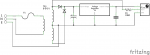
I'm building a project where I want to use the mains frequency for timing - my Picaxe 28X1 is running off 5 V and I have 9 V AC from the transformer. Space is tight so I want to limit component count if possible.
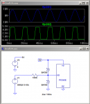
If I just connect 9V AC to an input pin via a suitable resistor - 100K say - am I right that the Picaxe's input protection diodes will happily protect the chip from damage, or do I need to add external diodes as well?
If I just connect 9V AC to an input pin via a suitable resistor - 100K say - am I right that the Picaxe's input protection diodes will happily protect the chip from damage, or do I need to add external diodes as well?
")