A picaxe based Segway project.

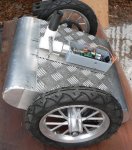
While I'm waiting for the new chips arrival, I thought I'll post another thread that I plan to do that is the Picaxe based Segway.
Gathered some information from Elektor Electronics magazines June, July/August, September issues about Elektor Wheelie a segway alike, and there were some free source in it, I could not attach the zip file probably cos is too large, so goto this link for download: http://www.badongo.com/file/26644591
I added 3 extra files in the 080718-11-v2.6 folder which were the PCB frabrication parts link: http://www.badongo.com/file/26644626
Open attachment for the part list used in Elektor wheelie,View attachment Components.txt
Anyone interested in building this projects in Picacaxe?
Please suggest a suitable Picaxe board for this project, thx
 

srnet

Senior Member
well I took a look at the website you linked to, gave up, far too much hassle wading throught the morass of dodgy downloads and adverts.

Posting a schematic will make it easier for people to help you.

As I recall the Segway needs sensors and the like to be read fairly quickly in a closed loop to control balance. I wonder if the PICAXE is fast enough ?

Looks a complex project, what is your experience level ?
 
Last edited:

BillyGreen1973

Senior Member
Seems like a good project, let us know when you've finished it and post details in the 'completed projects' section.

Just on another note. The file storage place you have used uses some 'interestingly placed' adverts to fool unsuspecting visitors to click the ads. This seems to be a little dangerous to me. Also, the files you have linked to are all copyright of the Elektor Magazine I think. I haven't downloaded them to see exactly whats in each download.

I would suggest using a file storage site like 'Box.com' they don't advertise on the download page in anyway.
 

Jeremy Harris

Senior Member
I've built a balancing scooter (see photo below of it minus the control arm), and can say with absolute certainty that there is no way on earth you'll get the PID loop to run fast enough on a Picaxe.

I just used the Zzaag design that was the predecessor to the one that Elektor produced as the Wheelie kit. The core processor and sensor PCBs as a package, together with some other parts, are still available from http://www.fun-components.com/index.php I believe, but the website of the chap that designed it, zzaag.org, seems to be just a bare Wordpress page now. I still have copies of the documentation for the Zzaag that I could post. The Zzaag runs an AVR Mega 32 that's running compiled code to get the speed up, but in my experience it's only just fast enough to produce a moderately stable scooter. Ideally the PID loop needs to be running a bit faster, I think, as mine tends to wobble a bit with no weight on it (adding weight increases the vertical pendulum time constant and makes the control problem simpler).

Trevor Blackwell has a good write up of the challenges of designing and building a balancing scooter on his website: http://tlb.org/scooter.html
 

Attachments

"far too much hassle wading throught the morass of dodgy downloads and adverts. " & "The file storage place you have used uses some 'interestingly placed' adverts to fool unsuspecting visitors to click the ads"

Will upload it to another file host.

"the files you have linked to are all copyright of the Elektor Magazine I think."

Yes, they were all downloadable from Elektor site, but the PCB is no longer included and I still have those file stored 2 yeas ago.

@ Jeremy, Thanks for the "Fun Components" link.


Here's the link for Elektor PDF and components list:

http://www.box.com/s/0177df1280b43ea2479c (schematic pdf)

http://www.box.com/s/dff89e83fd88b0dccbbe
 

Jeremy Harris

Senior Member
I've attached the source code for the Zzaag, the other files are too big, I'm afraid. The Zzaag firmware is very similar to the Elektor Wheelie, the only real difference being that the Wheelie has current limiting added, via a second AVR. Although this source code is a form of Basic, it needs to be compiled, as the control loop needs to run as fast as possible. You can get the balancing loop to run using just the P and I terms, but even so there's no way a Picaxe, even at 32 MHz, is going to do all the math and provide a fine enough PWM output, in the time needed to prevent the thing from oscillating in pitch. The code is pretty simple, as you can see, the key is in running it fast enough and with the right constants to get the loop to feel "right". Mine doesn't feel right at all, it's quite "mushy", which is indicative of the loop not running fast enough. The ATMega32 is running compiled code at 16 MHz (probably an order of magnitude faster than a Picaxe) and it still can't really do as good a job as I'd like. If you've ridden a Segway then you'll know that they are pretty stiff, which is an indicator that their control loop is running quickly with a short correction time constant. The Segway also uses BLDC motors, with a controller that is a lot more responsive than the simple H bridge PWM controllers that the Zzaag and Elektor machines use.
 

Attachments

westaust55

Moderator
Folks can also have a look at the Elektor website for the articles, etc.
June article pdf is only the front page but the July/Aug 2009 webpage has more details, schematic, PCB layout to download and software.
http://www.elektor.com/magazines/2009/july-047-august/elektorwheelie.984676.lynkx
More in the Sept 2009 edition. Free downloads here: http://www.elektor.com/magazines/2009/september/elektorwheelie.1041353.lynkx

Must register to download even the free articles.

@happytriger2000, I suggest that you heed to words of srnet:
Looks a complex project, what is your experience level ?
 

Jeremy Harris

Senior Member
It's not so much raw processor speed, but the speed at which it can execute the commands needed to run the proportional - integral - derivative control loop (or really just a proportional - integral control loop). In essence it's the same challenge that the people building quad copters have; measuring an error term using sensors, doing some math to calculate how big the error is and what direction it's in, then apply a correction factor back to the motors. This needs to happen quickly, or else the error will be different by the time the motors respond, so the correction won't be enough, the next error measured may then be bigger or in the other direction, leading to a correction being applied to the motors that may be too great, as by then they may be beginning to respond to the first correction. The result is either oscillation, or just a very sluggish response with a big zero error if you try and adjust the loop constants to reduce any overshoot.

The Picaxe runs interpreted Basic, which means that the code you have written has to be interpreted and converted into machine code by the built in firmware in the Picaxe chip every time it runs. This makes it much slower than compiled code, where all the work of converting high level code (like Picaxe Basic) into machine code is done by the PC and only the raw machine code runs on the µcontroller. Bear in mind that for good control in this application you want to be able to read the sensor ADCs, do the math and change the PWM at the outputs at a few hundred times a second, or thereabouts.

The Picaxe is intended for relatively undemanding tasks (in the time domain) and so is less well suited to fast control systems than some other systems. There isn't an intrinsic problem with using the PIC µcontrollers that the Picaxe is based on at much higher processing (not clock) speeds, but this would mean using a compiled language of some sort and programming raw PIC chips as required.
 
Folks can also have a look at the Elektor website for the articles, etc.
June article pdf is only the front page but the July/Aug 2009 webpage has more details, schematic, PCB layout to download and software.
http://www.elektor.com/magazines/2009/july-047-august/elektorwheelie.984676.lynkx
More in the Sept 2009 edition. Free downloads here: http://www.elektor.com/magazines/2009/september/elektorwheelie.1041353.lynkx

Must register to download even the free articles.

@happytriger2000, I suggest that you heed to words of srnet:
Yes it is quite complex project, the easiest way is to produce the PCB boards from Elektor, and get a AVR writer and burn the code.
 
Last edited:

Jeremy Harris

Senior Member
Yes it is quite complex project, the easiest way is to produce the PCB boards from Elektor, and get a AVR writer and burn the code.
Or you can just buy the Zzaag3 board from Fun Components (http://www.fun-components.com/index.php?route=product/product&product_id=89) and wire it up to a couple of batteries and a couple of motors and you're there! Not a particularly cheap option, but certainly pretty easy to build as it includes the motor controllers, sensors and AVR all on one board.

BTW, I've been experimenting this morning to try and see how fast the control loop runs on my DIY Segway. It seems to work at about 100 Hz, which is a bit slow and explains why it doesn't feel that firm. I believe it would feel better if I could get the control loop running at maybe double this speed. I'm also seeing just how fast a Picaxe can run a PID loop - initial results suggest that a few Hz is about it, so too slow for a project like this, as I thought.
 
Is it possible to use stand alone PID controller instead of writting a program to a MCU/picaxe?. Take DC servo Motor driver for example, it has PID control, it accepts cw/ccw or puls/dir.
 

Jeremy Harris

Senior Member
Is it possible to use stand alone PID controller instead of writting a program to a MCU/picaxe?. Take DC servo Motor driver for example, it has PID control, it accepts cw/ccw or puls/dir.
It's perfectly possible to make a pretty simple analogue balancing servo loop, probably simpler in many ways than doing it with a µcontroller. The basic circuit would be a complementary filter using op amps to sum the accelerometer and gyro signals, then a PID servo loop to control the motors. Getting the bandwidth would be easy enough and three pots could be added to allow the P, I and D constants to be adjusted to get good stability and a firm feel.

Alternatively, breaking the functions down and using a separate µcontroller for each *might* work. One µcontroller could read the gyro and accelerometer and do the angle calculation, using a digital complementary filter (or maybe a Kalman filter if you feel up to coding it in integer math!). The tilt angle could then be passed to another µcontroller that is only running a PID loop and controlling the motors. A third µcontroller could do the steering and look after housekeeping functions, like safety interlocks, current limiting, battery voltage monitoring etc.

Tilt angle probably only needs to be passed at a rate of maybe 50 times per second, the steering and housekeeping functions are probably less demanding (in terms of response time) so the critical element would be the PID loop controlling the motors. It's quite possible that a slightly simpler PD loop might be OK, which then gets close to being something a Picaxe *might* be able to do, especially if a separate controller was used for each motor, more or less halving the number of instructions that need to be run in each.

This would give a possible solution using four Picaxe µcontrollers, one doing tilt sensing, one doing steering and housekeeping and two doing motor control. Some work would need to be done to see if a Picaxe running at 32 MHz could control a motor quickly enough, but I suspect it might just be able to do it if it's not doing anything else.
 
Breaking the fuctions down might be the only option, as you mentioned before Picaxe might be too slow for PID, so let picaxe do the tilting and accelerating calculation, and a DC servo driver do the PID part: http://www.leadshine.com/UploadFile/Down/DCS810V2m.pdf.
For steering, if you look at this video I made:http://www.youtube.com/watch?v=HKFiGoenRX8, I use the encoder for steering, by the way that chip was pre-programmed I did'tn write the code, however there's a tutorial called spin and grin in Parallax, adapt the code.


hippy

Technical Support
Staff member
Is it possible to use stand alone PID controller instead of writting a program to a MCU/picaxe?
Probably. After all it's often the case that microcontrollers are simply modelling analogue systems with the advantage they are cheaper and can be more easily altered without extra hardware costs. The difficulties come in making the model as responsive and as accurate as the analogue system would be.

As well as PID there may be other options; Fuzzy Logic and so on.

In embarking on any major project it's usually advisable to have some experience of smaller but related projects first. Those teach the foundations to be used later and provide proof of concept knowledge. It may be worth looking at some of those before diving into what will be quite a challenging project as a full-sized self-balancing scooter.
 
Top