8M to turn on a Glow plug (1.5V at 1 Amp)

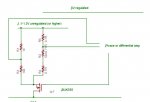
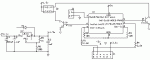
I need to determine the hfe (gain) value of the transistors that will drive the 1 Amp load. I tried to find the maximum amps from the output pins. The formula I'm using is:
Minimum transistor gain (hfe)=5*(load/max pin current).
I tried to find the max pin current from the 12F683 datasheet and (maybe I did not look in the right places) could not find it.
Any help or suggestions will be amply rewarded.
Thank you in advance
Andrés Rodríguez
 

Attachments

Last edited:

BeanieBots

Moderator
It's about 20mA from any pin.
There will be quite a lot of volt-drop across the transistor compared to the 1.5v supply. You might want to consider using a 1.5v plug with a 2v supply.
I had to do that because I was losing around 0.6v in the tranny. The 2v Cyclone cells make good plug supplies. Alternatively, use a relay.

Just checked your diagram.
You MUST put a resistor between the base and PICAXE output to limit the current or you risk damaging the output. Also consider the use of a FET transistor.
 
Last edited:

Rickharris

Senior Member
The data sheet for the transistor (or the supplier) should list the hfe. If not measure the collector current and base current. The gain is the amount the collector current is bigger than the base current.

www.rapidonline.com list the details for many transistors.
 
Thank you

Thank you for the suggestions gentlemen.
Beanie, what value do you suggest for the resistors between the base and the output pin?
 

moxhamj

New Member
A BUK555 mosfet can be driven directly from a picaxe with no other components as it switches from 5V with virtually no current. Plus it will hardly even get warm at these currents.

Just be careful about the max current through a glowplug. Driving off 1.2V is fine but 2 nicads will cook a glowplug. I once designed a circuit that measured the resistance of the glowplug in between pulses (resistance=temp) and adjusted the pulse width accordingly. It was quite a few components - these days a picaxe would do the job nicely.
 

BeanieBots

Moderator
No less than 220R.
That will give about 20mA into a base which is ~0.6v above ground.
Personally, I'd go with the FET suggested by Dr_Acula.
 

Michael 2727

Senior Member
I'd go with a MOSFET also.
Look at the PWM Supply in the finished projects Misc section.
You could include some current monitoring as this is what it is
really all about, making sure you don't fry the platinum glow coil.
( the voltage can be anything from 1.5V to 20V current limited )

As I recall a single drop of fuel in a flooded motor can greatly
reduce the coil temperature temporarily. Some current monitoring
with an auto adjustment/limiting would give you the best practical
supply to use and is well within the capability of an 08M picaxe.

There has been many a discussion on current monitoring, you
may have to do the dreaded "search" ( which the younger ones
seem to have an allergic reaction to ) the info is there.

A 12V DC (car battery) PWM, Current Monitored/Limited/Adjusted
supply would give you best unit on the block.
 

BeanieBots

Moderator
Maybe I've missed something but all I've ever done is 2v plug, single Pb cell, switch and moving coil ammeter. The ammeter being a real cheap moving iron type like those found in battery chargers simply to indicate that current is flowing. ie good connection and battery not flat.
Never had any trouble starting except when something wrong with engine rather than the plug.
Correct plug type is important. Long/short reach. Maybe drop a washer size for worn out engines.
Why the need for electronic switching let alone current monitor/control?
 

moxhamj

New Member
Certainly electronic glow plugs work and they work well especially at low revs and for starting. But an old timer RC modeller pointed out an even simpler solution - he had a microswitch hooked up to the throttle servo and when it went below a certain value it connected a single 1.2V nicad. It only ever was on when coming in to land (and of course one doens't want the engine to cut out at that point) so the battery lasted forever and it was very simple as it only used a battery and a switch.
 
Beanie and Dr-Acula, I am new to the programming and electronics field. But I have built and flown RC airplanes for 40 years. I have used the micro switch approach and it works. However, any adjustments are made by sliding the switch and/or the servo. Not very accurate and cumbersome in the flying field. But it is OK in many cases. In this case I am working on a Laser 200 (20cc) four stroke engine. It has 2 cylinders in V configuration and two carburators. It is imposible to have exactly the same mixture in both cylinders. Therefore, if one cylinder goes rich at low speed, it could (and will) extinguish the glow plug. When that happens, the cylinder that is still running is fighting the drag of the other.
Meassuring the resistance (temperature) of the two glow plugs may allow me to send power to the colder plug and that way if the other cylinder is still running it will re-ignite the dead one.
As I stated before, I am new to this technology so I may be trying to do the impossible but this is the best place to ask these questions.
By the way I never saw a 2V glow plug. Although I understand that they are used in racing RC boats running up to 75% nitromethane in the fuel. The plugs used in airplanes are designed for 1.5V (we used dry cells or a single cell from old car lead/acid batteries). Today all the glow plug drivers use NiCad or NmHi 1.2V cells.
Thank you for your interest guys.
 

moxhamj

New Member
Attached is a starting point. This puts the glowplug in a bridge configuration. R4 and R5 are wires going to the glowplug - 30cm of thick hookup wire. You can calibrate these by passing a known 1 amp and measure the volts. The value is a compromise - too low and the values are out of range for readadc10 and too high and the wires get hot and waste energy. If the glowplug is 1.5A at 1.5V then it is around the 1 ohm mark when hot and a ratio of 10:1 on the bridge still gives accuracy without needing an op amp. When the glowplug is cold it has a much lower resistance.

The other trick is that the sense wire at the high side of the glowplug needs to be a physical wire connected to the top of the glowplug - so the glowplug has 3 wires going to it.

Turn on the mosfet and then sample the values on the sense wires. The value at the top of the glowplug will start low and will rise as it warms up. The value between the 1k/10k will fall as the battery load increases and the volts fall on the battery. Leaving out R5 for the moment this is just a standard bridge circuit where the difference is the important value. R5 can be thicker wire if needed.

Alternatively R1 and R2 can be left out and if R4 is known accurately the volts across this could be measured and the amps calculated and if the supply volts are measured and known then V=IR the resistance of the glowplug can be calculated. Either way would work.

I remember doing lots of experiments with 1 nicad before I was confident it was working well enough to move up to 2 cells as 2 cells can cook a glowplug but 1 won't. I also found one needed to solder wires onto the glowplug - push on connections changed their resistances and the calculations varied.
 

Attachments

Last edited:
Top