I built a window ornament for the Christmas season a couple of years back. The main part is a PICAXE 14M2 that controls eight independent channels that power LEDs. The whole star is made up of eight circuits of 5 LEDs each.
The program works by reading light “patterns” stored in the eprom and writing directly to port b and port c.
Each light pattern program consists of an entry that specifies the number of lines the pattern consists of, an entry that specifies the length of pause before the pattern switches to its next line, and the pattern itself, which consists of an easy to read binary number. Basically, you can figure out what the pattern will look like by looking at the pattern of “ones” and “zeroes” in the binary code. Since each pattern has its own entry for the pause duration, all patterns can run at different speeds.
The first fifteen eprom bytes (0-14) are reserved as addresses, so the main program knows where to look for the next pattern data.
After running each pattern for 20 cycles, the program will shift to the next pattern, and restart at the first one after the last one has been played.
Creating a new pattern is as easy as writing a new pattern set into the eprom (aka “data”) lines of the code, specifiy the relevant start of the pattern in one of the first fifteeen eprom spaces, and, if needed, specifiy the number of program slots in the “basic configuration” part of the program in the variable “maxprogram”.
If you take a look at the program, you will notice that I wrote a big chunk of commentary at the beginning that states which pin on the PICAXE does what and where in memory the variables live. I found that a useful tool, because in most cases the I build the circuit after writing the program. Especially the memory locations table helps me to avoid writing the same variables to the same location, or for example using w2 and b4 and b5 for different things, as they they are stored in the same address. Trust me, I messed that up a couple of times when I first started PICAXEing, and it has thrown me off every time. But now, thanks to the comment section, nevermore.
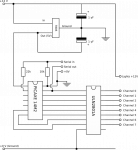
The circuit is simplicity itself.
Main power is provided by a 12 V wall adapter.
A simply voltage regulator with two capacitors drops that down to 5 Volts for the PICAXE 14M2. The Picaxe is connected to a ULN2801A darlington transistor array that will sink the LED channels to ground if the relevant port on the PICAXE goes high.
The LED circuits are directly connected to the 12 Volt power supply and sink to the darlington array, and that is that.
I built the circuit on a small piece of strip board. I like the stripboard better than the “dot” type of prototyping board, because I find it easier to remember to break a few connections to make it work, instead of creating all of the connections between components on my own. I’ve done that, but it always turned into a big mess of solder with unwanted solder bridges all over the place. But by any means, if you, dear reader, are happier working on the “dot type” board, then go for it.
The wooden star I chose was created for me by a friend who has a CNC router. The PICAXE on its circuit board is prominently displayed on the front of the star. On the back side is a true rat’s nest of wires; since 12 volts turned out not to be enough to power 5 LEDs in a row, I had to break each LED channel down into a group of 3 and a group of 2 to make it work.
I mad the mistake of chosing ultrabright LEDs for this project; they turned out to be so bright that their shine was visible on the neighbors house about 40 metres away. I found that I couldn’t just turn the voltage down a bit, as that caused the brightness to drop way down on the group of 3 LEDs in each channel. In the end, I just took a sharpie and painted a black dot on top of each LED, and that solved that problem nicely.
All in all, this circuit and program is something that could be used for any type of pattern lighting with eight channels.
You can watch it running here:
This is a picture of the whole thing in the light:

The program works by reading light “patterns” stored in the eprom and writing directly to port b and port c.
Each light pattern program consists of an entry that specifies the number of lines the pattern consists of, an entry that specifies the length of pause before the pattern switches to its next line, and the pattern itself, which consists of an easy to read binary number. Basically, you can figure out what the pattern will look like by looking at the pattern of “ones” and “zeroes” in the binary code. Since each pattern has its own entry for the pause duration, all patterns can run at different speeds.
The first fifteen eprom bytes (0-14) are reserved as addresses, so the main program knows where to look for the next pattern data.
After running each pattern for 20 cycles, the program will shift to the next pattern, and restart at the first one after the last one has been played.
Creating a new pattern is as easy as writing a new pattern set into the eprom (aka “data”) lines of the code, specifiy the relevant start of the pattern in one of the first fifteeen eprom spaces, and, if needed, specifiy the number of program slots in the “basic configuration” part of the program in the variable “maxprogram”.
If you take a look at the program, you will notice that I wrote a big chunk of commentary at the beginning that states which pin on the PICAXE does what and where in memory the variables live. I found that a useful tool, because in most cases the I build the circuit after writing the program. Especially the memory locations table helps me to avoid writing the same variables to the same location, or for example using w2 and b4 and b5 for different things, as they they are stored in the same address. Trust me, I messed that up a couple of times when I first started PICAXEing, and it has thrown me off every time. But now, thanks to the comment section, nevermore.
The circuit is simplicity itself.
Main power is provided by a 12 V wall adapter.
A simply voltage regulator with two capacitors drops that down to 5 Volts for the PICAXE 14M2. The Picaxe is connected to a ULN2801A darlington transistor array that will sink the LED channels to ground if the relevant port on the PICAXE goes high.
The LED circuits are directly connected to the 12 Volt power supply and sink to the darlington array, and that is that.
I built the circuit on a small piece of strip board. I like the stripboard better than the “dot” type of prototyping board, because I find it easier to remember to break a few connections to make it work, instead of creating all of the connections between components on my own. I’ve done that, but it always turned into a big mess of solder with unwanted solder bridges all over the place. But by any means, if you, dear reader, are happier working on the “dot type” board, then go for it.
The wooden star I chose was created for me by a friend who has a CNC router. The PICAXE on its circuit board is prominently displayed on the front of the star. On the back side is a true rat’s nest of wires; since 12 volts turned out not to be enough to power 5 LEDs in a row, I had to break each LED channel down into a group of 3 and a group of 2 to make it work.
I mad the mistake of chosing ultrabright LEDs for this project; they turned out to be so bright that their shine was visible on the neighbors house about 40 metres away. I found that I couldn’t just turn the voltage down a bit, as that caused the brightness to drop way down on the group of 3 LEDs in each channel. In the end, I just took a sharpie and painted a black dot on top of each LED, and that solved that problem nicely.
All in all, this circuit and program is something that could be used for any type of pattern lighting with eight channels.
You can watch it running here:
This is a picture of the whole thing in the light:
Last edited: