5vdc latching relays @ 40 cents each!

leftyretro

New Member
We probably don't want to see a bunch of commercial offerings on this forum but I thought this deal too good to not let those interested know about.

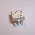
I've no attachment to seller other then having bought 10 of them recently. These are 5 volt, single coil, 2 amp DPDT contacts, latching relays in a DIP package (however with short leads that aren't long enough to pull into my solderless breadboard).

At 5v I measure 17ma current draw so driving from picaxe outputs is possible and has worked fine on my 28X1. You only have to pulse the winding for around 10ms to set or reset it. Listing includes a linked data sheet. Listing shows 2124 units still avalible.

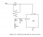
As I'm sure some of you know, latching relays can be used in some pretty tricky applications.

Lefty

http://cgi.ebay.com/Miniature-Single-Winding-Latching-Relay-5V-DC-DIP-2A_W0QQitemZ120096057860QQihZ002QQcategoryZ42897QQcmdZViewItem
 

Tom2000

Senior Member
Good find, Lefty. Thanks!

If they work as advertised in the auction description (positive pulse on, negative pulse off) you could "half charlieplex" these relays, giving you 28 relays controlled by the 8 bidirectional pins on a 28X1's Port C.

Buy more. :)

Tom
 

WHITEKNUCKLES

New Member
Last edited:

tmack

Member
Relay

Sorry to be dumb but is there a different use for the mos relays as opposed to the "normal" relay type.
 

Tom2000

Senior Member
As long as you stay within the ratings, not really. (These are rated for 350 volts/120 mA.)

I use one of these - a dual - in another project simply to save board real estate over that used by a couple of reeds.

One difference, other than size, weight, and power consumption is that these don't bounce. Reeds don't bounce much, but these don't bounce at all.

When applying one of these, remember that you're driving an LED. You need to add current limiting resistance on the input, just as you would with a discrete LED.

Tom
 

Tom2000

Senior Member
Cool! And if you're interested in duals (8 pin PDIP), some part numbers are LAA110, PAA110, and PVT322A. There are others.

Tom
 

Fletch

Member
I'm curious about that myself. If you recall I am looking at adding remote control to a few pre-existing circuits and the conclusion was that relays were the safest option. Can these silicon relays be used instead? Does this mean we dont need a driving transistor or a reverse bias diode (ie can it be directly connected to a picaxe pin (though a resistor?)
 

Tom2000

Senior Member
Fletch, that's correct. When you drive one of these, you're driving an LED, so you handle it just like an LED. Current limiting resistor and everything. And, no coil means no spikes on release, so you don't need a suppression diode.

Shafto, sort of answering your question, once you fire an SCR, the current through it must decay to zero or reverse polarity before the SCR releases, so it's used to drive pulsing or AC sort of stuff. A relay is, well, a relay. It turns on and off when you tell it to, not when the signal tells it to.

Tom
 

andrew_qld

Senior Member
I've never seen a quad. Just singles and duals.
Tom
We regularly use 4 pole relays at work for switching stereo ballanced audio. They are fairly rare in smaller relays and I have only seen smaller PCB types available in one or two types from the likes of Farnell and RS.

And on the relay vs SCR / solid state relays topic:
It used to be in the old days that "normal" relays drew too much current to use directly with a microprocessor (you had to use a transistor to switch them) and solid state relays could be driven with a micro as they needed very little current to hold them on.

These days this is not as important, especially with reed relays that only draw 10-20mA (you still need a "back EMF" protection fdiode though). If I am switching more than 12v or so I like to use a relay as (to my mind anyway) they tend to offer more isolation and are safer. But once again, this is less of an issue these days.
 
Last edited:

leftyretro

New Member
If it's single-coil, beware the back-emf when the relay "releases". PicAxe don't like spikes.
Yea, because the relay set and reset is done by reversing polarity the simple reverse diode across the winding won't work. Back to back zener diodes across the coil might work OK. So far I've had no problems with using the 28X1 unprotected. possible because it's such a low current winding the counter EMF pulse may be small.

Any one got a simpler solution?

Lefty
 

tmack

Member
Relays

I recieved my relays in the mail yesterday. They are awesome. Very small. I bet there are alot of uses for these.
 

tmack

Member
Can anyone help me figure out what Im doing wrong? I cannot get these to work. I tried applying 5v in both directions across the coil (pins 1,10). I couldnt get the poles to switch on my relay.
 

tmack

Member
I think they are awesome. My first application is using them on a sequencing circuit I built with others help from this forum a little while ago.I want to be able to go through my relays turning one on and the others off in a sequencial fashion. I am just a little confused though. The coil only changes its position when the voltage is reversed right? so if I need it to change from open to closed I have to figure out how to switch the "+" and "-" to the poles of the coil? Im not really sure ho to do this with the Picaxe.Anyone have any ideas? maybe just a quick code to turn the relay on and then off. I understand that it takes a 10 ms pulse to turn it on but how do I change it back after that? Thanks for any help.
 

leftyretro

New Member
I think they are awesome. My first application is using them on a sequencing circuit I built with others help from this forum a little while ago.I want to be able to go through my relays turning one on and the others off in a sequencial fashion. I am just a little confused though. The coil only changes its position when the voltage is reversed right? so if I need it to change from open to closed I have to figure out how to switch the "+" and "-" to the poles of the coil? Im not really sure ho to do this with the Picaxe.Anyone have any ideas? maybe just a quick code to turn the relay on and then off. I understand that it takes a 10 ms pulse to turn it on but how do I change it back after that? Thanks for any help.
The easiest way takes two digital output pins from the picaxe. A high on one pin and a low on the other will switch it to one state, reversing the high and low to the opposite pins will change it to the other state. Leaving both pins high or low will result in no current being consumed by the relay coils and they remain it their last state.

Lefty
 

tmack

Member
ah ha I was kinda thinking that but I thought there might be a way to do it with only one pin. Thanks.Ill switch from a 08 to an 18 for this project.
 

lbenson

Senior Member
>Can anyone help me figure out what I'm doing wrong? ... Figured it out.

Could you supply the pinouts?
 

BeanieBots

Moderator
It should be possible to switch them with just one pin.
Just put a large (non polarized) capacitor in series with the coil.
It works with 12v relays but the charge held by a non-polarized cap (usually around 10uF max commonly available) might not be enough on 5v. Worth a try.
 

leftyretro

New Member
It should be possible to switch them with just one pin.
Just put a large (non polarized) capacitor in series with the coil.
It works with 12v relays but the charge held by a non-polarized cap (usually around 10uF max commonly available) might not be enough on 5v. Worth a try.
Wow what a great idea!

First I bread boarded a quick hook-up of one side of the coil to +5vdc other side of coil to the + side of a 22mfd 50vdc elec. cap, - side of cap manually moved to ground or +5vdc and the contacts switched with each transition.

Next with the same setup I hooked the - side of the cap to a picaxe output pin that is toggling around 4hz (also tried a 2 second pulse which also worked) and relay contacts continued to switch reliably.

So it's not a non-polarized cap and I don't know how much stress the picake might be seeing, but the results seem to work perfect.

Great solution that only uses one output pin but still utilizes the zero steady state coil current capability of a latched relay coil, it just switches during the transitions of high to low or low to high.

BB you are a genius ;)

PS: I guess some testing might be needed on what happens on start-up of first powering up the picaxe/cap/relay circuit. Wouldn't want an unintended transistion to occur.
 
Last edited:

BeanieBots

Moderator
Actually, I'm a plank!
The cap CAN be polarised. The -ve end connected to 0v, the +ve to the coil, other end of the coil to PICAXE output.
The cap will never be reversed and can therefore be a regular electrolytic.
 

leftyretro

New Member
Actually, I'm a plank!
The cap CAN be polarised. The -ve end connected to 0v, the +ve to the coil, other end of the coil to PICAXE output.
The cap will never be reversed and can therefore be a regular electrolytic.
Yes that works well, I see no strange voltage spikes on my o-scope. By the way I tried 10mfd and it did not work, but 22mfd does. I don't have any thing between those values handy to test with.

Lefty
 

BeanieBots

Moderator
Bigger would be better for reliable operation.
I'd go for around 470uF to be confident of gauranteed switching.
The only reason I suggested 10uF initially was because it is hard to find non-polarised bigger than 10uF.
The cap needs to be large enough to have enough charge to trip the relay.
Making it very big simply means having to wait for it to charge/discharge through the coil before switching again.
Not sure what the coil resistance is, but it will be quite low so several hundred uF will be OK for switch speeds of sub 1S.
If you want to switch quicker than that, then by all means experiment to find the 'optimum' value which sounds like it might be around 22uF, but consider the life of the poor old mechanical device at that sort of speed!
 

leftyretro

New Member
Drawing of latching relay used as auto turn-off

Well I finally loaded a free schematic drawing program, ExpressSCH, and thought I would document the use on one of these single coil latching relays used is a typical auto shut-off application. I'm showing a 08M chip but the design would work with any of the Picaxe chips.

The Picaxe is started by pressing the monetary push button switch. The first instructions in the Picaxe program would be a high 1 command. This would activate the relay and the push button can then be released, just takes about 10msec to latch up. At anytime in the program when you want the Picaxe to power down just GOTO a low 1 command and the lights turn off :)

The cap allows us to only need one output pin to turn on and off the relay, otherwise two outputs would be required as the relay sets or resets depending on the direction of current flow through it's coil. The resistor helps to discharge the cap when powered down to allow immediate re-powering up if wanted, otherwise with out the resistor the cap is a bit slow to self discharge and restarting may not work reliably.

The advantage of this method of auto turn off is that there is zero current used while in the off mode and only 250ua extra (the resistor load) used while powered up. Also there is an extra unused set of SPDT contacts available for use.

The only thing to keep in mind is about program downloading. The device has to be programmed in the 'cold reset' method. Power off the +5vdc, start the download, then power up the +5vdc supply and then press and hold the monetary power start switch. You must hold the switch down until the editor completes the download and then lets your program start with a high 1 command, otherwise the relay will not have been commanded on and power for the Picaxe will drop if you release the switch before downloading completes.

Anyone that hasn't yet ordered these relays should check them out. That E-bay seller still has some 800 available last I checked and at $ .40 each has to be the component value of the decade. I'm trying to decide if the 10 I bought is enough to have stashed away. ;)

EDIT: I see I made a mistake in the drawing, The capacitor must be 22mfd or larger. I'll see if I can edit and reload the drawing.
Lefty
 

Attachments

Last edited:
Top