Complete writeup is at:
http://www.instructables.com/id/Build-a-500-metre-radio-data-link-for-under-40./
A few tricks:
Use a higher power Tx module.
Use the most sensitive Rx module (superheterodyne)
Get the RF up high with some coax
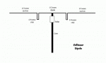
Use a dipole
Use a balun
Add a preamble
Keep the number of 1's and 0's in a packet roughly equal
Use a checksum
Use a dipole on the Rx
Test the range, and decrease the power if it goes further than your property boundary!
http://www.instructables.com/id/Build-a-500-metre-radio-data-link-for-under-40./
A few tricks:
Use a higher power Tx module.
Use the most sensitive Rx module (superheterodyne)
Get the RF up high with some coax
Use a dipole
Use a balun
Add a preamble
Keep the number of 1's and 0's in a packet roughly equal
Use a checksum
Use a dipole on the Rx
Test the range, and decrease the power if it goes further than your property boundary!
")