28X2 to drive a Rev-Ed 4x20 OLED to tell the time with a DS3231

David_Reynolds

Well-known member
I am being stupid again.
You are going to stick it with a permanent magnet on the end of an actuator, then pull it off when the power returns and the clock timer matches the stored time, I get it. you will have plenty of battery power to do this small thing, then once it is done the only power needed is the electronic clock
Sorry, forget I asked, carry on
 

Rampz

Well-known member
here's some code to try on a 20x2 just add your oled and rtc
it seemed to work ok
just hit program (make sure to close the serial terminal first)
and dont move the mouse I find it sometimes delays the programming
Thank you Marks i will give it a go, i haven't yet drictly connected an oled to a picaxe in this way, i do have one to play with on the AXE091 development board, mine is a 4 line version from Rev-ed so hope it will be ok
 

Rampz

Well-known member
My preference is for a button which resets to 'the nearest hour'. That way it's easy to sync things up to 'on the hour pips' or other references.
Hippy i could see a lot of waiting, so maybe to the nearest minute would be better.

I did see your comments regards the idea of not programming the DS3231 for BST and rather display an altered time and leave the DS3231 alone

The only way to do that would be to disable the internal clocking and then enable it again, and one would have to try it to see if it actually works.

But do you really need it "spot on" ? How would you even know it was 100ms out of sync ?
Good point, it was more that very slight differences could be seen between say laptop time and DS3231 time and a way to inch it closer, but yep guess i don't need the time so accurate, but as the time wanders off during the year a few seconds it would be good to be able to correct for that and yes leave the ageing register alone for the moment.

I suppose for the events i want to deal with this project the accuracy will be enough, if there is a power fail i will stop the clock and then restart it at the same time after mains is restored, so regardless of clock error i will only need to stop and restart say over max couple of weeks so the inaccuracy will be very small
 

Rampz

Well-known member
I am being stupid again.
You are going to stick it with a permanent magnet on the end of an actuator, then pull it off when the power returns and the clock timer matches the stored time, I get it. you will have plenty of battery power to do this small thing, then once it is done the only power needed is the electronic clock
Sorry, forget I asked, carry on
This is currently being done for summer winter change over on a regulator run by a PLC, the actuator moves out with a permanant magnet and stops the pendulem at the limit of its swing, then when its time to restarts the actuator pulls back releasing the pendulem to restart the clock, just nobody does this system to take account of a power fail situation, the norm being that you have to climb the clock tower of your church after a power cut and restart the clock, set the time and make sure the chimes match the time, this system is to prevent this being needed.

No power is needed to keep the pendulem stopped, only the reversing of the actuator is needed to start the clock, the pendulem is forced away from the magnet by the design of the actuator, not by just moving away which would result in a huge swing of the pendulem
 

Jack Burns

New Member
Jack Burns have you got a bit of code to do the seconds zeroing?
It's old code so not very well documented.

The RTC needs to be preloaded with a valid date and time before running this code, as this is basically a clock display (date/time) with a button to sync the time to the nearest minute (it has no other setting facility).

Output format:
25.03.2022 09:10:02

Rich (BB code):
' DS3231 RTC with onboard AT24C32 EEPROM
'
' This code will adjust the time to the nearest minute when the SyncButton is pressed.
'
' NOTE:
' Will NOT work one minute to midnight as date rollover is NOT catered for.
' 
'
'
' CONNECTIONS:
' DS3231 Connects to C.1 & C.2 (SCL & SDA), 0V & V+
' SyncButton connects between C.3 and V+.  C.3 is held low with a resistor.
'
#picaxe 08m2
#no_data
#terminal 4800

symbol secs     = b0
symbol mins     = b1
symbol hour     = b2
symbol dow      = b3
symbol day      = b4
symbol month    = b5
symbol year     = b6
symbol century  = b7
symbol control  = b8

symbol lastsec = b14
symbol d1 = b15 ' 1st digit of bcdtoascii conversion + tempbyte1
symbol d2 = b16 ' 2nd digit of bcdtoascii conversion + tempbyte2

symbol SyncButton = pinc.3

hi2csetup i2cmaster, %11010000, i2cslow, i2cbyte


do
  do
    hi2cin 0, (secs, mins, hour, dow, day, month, year)
    pause 10
    if SyncButton = 1 then
      gosub SyncTime
    endif
  loop until secs<>lastsec
  lastsec = secs
  gosub ShowTimeOnTerminal ' prints date & time
loop


SyncTime: ' sync time to nearest minute when SyncButton is pressed.

  if secs > $29 then ' go to next minute if 30 secs or more
    gosub IncMinute
  endif
  
  secs = 0
  lastsec = secs
  gosub ShowTimeOnTerminal ' UpdateTimeDisplay
  
  do
  loop while SyncButton = 1 ' hold time until button is released
  hi2cout 0,(secs,mins,hour) ' update RTC
  return


IncMinute:
  ' Set time to next minute only if the date remains the same.
  if mins = $59 and hour = $23 then
    sertxd("Date Rollover NOT coded, therefore Time NOT adjusted",cr,lf)
  else
    d1 = mins : gosub IncBcd : mins = d1
    if mins = $60 then
      mins = 0
      gosub IncHour
    endif
  endif
return


IncHour:
  d1 = hour : gosub IncBcd : hour = d1
  return


IncBcd:
  d1 = d1 + 1
  d2 = d1 & 15
  if d2 > 9 then
    d1 = d1 + 6
  endif
  Return


ShowTimeOnTerminal:
  bcdtoascii day,d1,d2   : sertxd(d1,d2,".")
  bcdtoascii month,d1,d2 : sertxd(d1,d2,".")
  bcdtoascii year,d1,d2  : sertxd("20",d1,d2,"  ")
  bcdtoascii hour,d1,d2  : sertxd(d1,d2,":")
  bcdtoascii mins,d1,d2  : sertxd(d1,d2,":")
  bcdtoascii secs,d1,d2  : sertxd(d1,d2,cr,lf)
  return
 

Rampz

Well-known member
Just spending a few days to see what the accuracy of the DS3231 is like, seems either the laptop is not keeping good time or the module, after only 4 days we are 5 seconds different, checked the laptop time and found that its 43 seconds wrong anyway, so accuracy is one thing but what to measure it against? Set laptop to different time server seems it will update every 9 hours or so, should keep better time to check module against
 

Rampz

Well-known member
here's some code to try on a 20x2 just add your oled and rtc
it seemed to work ok
just hit program (make sure to close the serial terminal first)
and dont move the mouse I find it sometimes delays the programming
Thanks Marks, i am using a 4 line oled display from Rev-Ed it took several minutes to get the display to light up, what do i need to alter to make use of the 4 line display against the 2 line in your code? Currently i have odd symbols all over the screen and from time to time i get the time somewhere in the mess, its fine on the terminal.

Also looking for info online to explain
Code:
TABLE   0, ($3,$3,$2,$2,$8,$0,$C,$0,$1,$0,$2,$0,$6)
'(4Bit)(2line/5x8)(Display On)(Clear Display)(Return Home)(Entry Mode Set)
I have had a look though the data sheet for the oled and can't make sense of it, what am i looking at?

Edit

From what i can work out the command code sequence required to initialise the display is likely correct for either a 2 line display or the 4 line i am using, i guess it needs sending in this format since its in 4-bit, whereas in 8-bit mode it can be sent differently, so for me i guess the issue is somewhere else, for why i am getting other data all over the place.


Ok so i can see that the data for each command is send to 2 halves
i can work out that $0,$C is in Hex= Display On.

But for the whole string there is an odd number of numbers, with them being set in 2 halves which one is the odd one out?

Reading all over the net, somewhere it says that it sends hex $3 three times to make sure its in 8 bit mode then sends the 8 bits that adds upto 40 being 32 + 8 which in hex is 28, so looks like the start should be $3,$3,$3,$2,$8 and then the rest, so since what i am is slightly different, i wonder if thats causing the issue, but it explains why i have an odd number of half bits.

Still waiting a week to see how the clock performs against the laptop now the laptop is being updated time wise every 9 hours i think.

I have ordered the Rev-ed gps module since for future projects that may well be the way to go, but for this project i think this will be fine
 
Last edited:

tmfkam

Senior Member
TABLE 0, ($3,$3,$2,$2,$8,$0,$C,$0,$1,$0,$2,$0,$6)
'(4Bit)(2line/5x8)(Display On)(Clear Display)(Return Home)(Entry Mode Set)

That looks like the command code sequence required to initialise the display. It sends the commands in the correct order for those stated underneath. The codes are shown in hex, possibly listed in decimal in the datasheet?

If you are using a Rev-Ed display with a back pack (I thought you were?) you shouldn't need those unless this code is for the processor on the back pack? It also seems as though the comment suggests that code is for a 16 x 2 display, that command would be where you would need to select your type of display.
 

Rampz

Well-known member
If you are using a Rev-Ed display with a back pack (I thought you were?) you shouldn't need those unless this code is for the processor on the back pack? It also seems as though the comment suggests that code is for a 16 x 2 display, that command would be where you would need to select your type of display.
Tmfkam, someone posted code for the 20x2 driving an oled in 4bit, it was for the 2 line and i only have a 4 line, so thought i would give it a go, ultimatley i would like to keep the quantity of picaxe's in my project to the minimum and using the backpack is currently the easy route, but since it was posted i thought i would try it, it didn't go so well, so thought best try and learn more about doing it etc
 

cpedw

Senior Member
Also looking for info online to explain
Code:
TABLE   0, ($3,$3,$2,$2,$8,$0,$C,$0,$1,$0,$2,$0,$6) 
'(4Bit)(2line/5x8)(Display On)(Clear Display)(Return Home)(Entry Mode Set)
I have had a look though the data sheet for the oled and can't make sense of it, what am i looking at?
[/QUOTE]
The OLED controller's datasheet has the answers. It's not an easy read but I recommend starting about page 18, 21 then 23-25.
 

hippy

Technical Support
Staff member
[/QUOTE]
i am using a 4 line oled display from Rev-Ed it took several minutes to get the display to light up, what do i need to alter to make use of the 4 line display against the 2 line in your code?
You shouldn't have to do anything other than send the correct address for the start of the line you want to write to before writing the data for that line.

This is the standard OLED initialisation I use on the AXE133Y -
Code:
; .-----------------------------------------------------------------------------.
; |    AXE133Y OLED Template                                                    |
; `-----------------------------------------------------------------------------'

#Picaxe 18M2
#No_Data

; .-----------------------------------------------------------------------------.
; |    Variables                                                                |
; `-----------------------------------------------------------------------------'

Symbol reserveW0 = w0 ; b1:b0

; .-----------------------------------------------------------------------------.
; |    LCD connections                                                          |
; `-----------------------------------------------------------------------------'

Symbol pinE  = pinC.6 : Symbol dirE  = dirC.6   ; 0 = Idle      1 = Active
Symbol pinRS = pinC.7 : Symbol dirRS = dirC.7   ; 0 = Command   1 = Data

Symbol pinD0 = pinB.0 : Symbol dirD0 = dirB.0   ; LCD Data Line 0
Symbol pinD1 = pinB.1 : Symbol dirD1 = dirB.1   ; LCD Data Line 1
Symbol pinD2 = pinB.2 : Symbol dirD2 = dirB.2   ; LCD Data Line 2
Symbol pinD3 = pinB.3 : Symbol dirD3 = dirB.3   ; LCD Data Line 3
Symbol pinD4 = pinB.4 : Symbol dirD4 = dirB.4   ; LCD Data Line 4
Symbol pinD5 = pinB.5 : Symbol dirD5 = dirB.5   ; LCD Data Line 5
Symbol pinD6 = pinB.6 : Symbol dirD6 = dirB.6   ; LCD Data Line 6
Symbol pinD7 = pinB.7 : Symbol dirD7 = dirB.7   ; LCD Data Line 7

; .-----------------------------------------------------------------------------.
; |    Main Program                                                             |
; `-----------------------------------------------------------------------------'

PowerOnReset:

  Gosub InitialiseLcd

MainLoop:

  b0 = %00000001 : Gosub SendComdByte ; Clear screen
  b0 = %10000000 : Gosub SendComdByte ; Home
  Do
     b0 = "X" : Gosub SendDataByte
     Pause 1000
  Loop

; .-----------------------------------------------------------------------------.
; |    LCD initialisation routine                                               |
; `-----------------------------------------------------------------------------'

InitialiseLcd:

  dirE  = 1             ; Set LCD control lines as outputs
  dirRS = 1
  dirD0 = 1
  dirD1 = 1
  dirD2 = 1
  dirD3 = 1
  dirD4 = 1
  dirD5 = 1
  dirD6 = 1
  dirD7 = 1

  Pause 500

  For b1 = 0 To 7
    LookUp b1, ( $33,$33,$33, $3B,$0C,$06,$1F,$01 ), b0 : Gosub SendInitCmdByte
  Next

  ; Nibble commands - To initialise 8-bit mode
  ;
  ;   $33       %0011----               8-bit
  ;   $33       %0011----               8-bit
  ;   $33       %0011----               8-bit
  ;
  ; Byte commands - To configure the LCD or OLED
  ;
  ;                 LNFff
  ;   $3B       %00111011               Display Format
  ;
  ;               L : 0 = 4-bit Mode    1 = 8-bit Mode
  ;               N : 0 = 1 Line        1 = 2 Lines
  ;               F : 0 = 5x7 Pixels    1 = N/A
  ;
  ;               f : OLED Font table   00 English-Japanese
  ;                                     01 Western European 1
  ;                                     10 English-Russian
  ;                                     11 Western European 2
  ;
  ;                   DCB
  ;   $0C       %00001100               Display Control
  ;
  ;               D : 0 = Display Off   1 = Display On
  ;               C : 0 = Cursor Off    1 = Cursor On
  ;               B : 0 = Cursor Steady 1 = Cursor Flash
  ;
  ;                    IS
  ;   $06       %00000110               Cursor Move
  ;
  ;               I : 0 = Dec Cursor    1 = Inc Cursor
  ;               S : 0 = Cursor Move   1 = Display Shift
  ;
  ;                  GP
  ;   $1F       %00011111               Graphics Mode
  ;
  ;               G : 0 = Text Display  1 = Graphics Mode
  ;               P : 0 = Int Power Off 1 = Int Power On
  ;
  ;   $01       %00000001               Clear Screen
  ;
  ; Additional OLED Graphics commands
  ;
  ;   $80       %1xxxxxxx               GXA
  ;
  ;   $40       %0100000y               GYA 

  Return

; .-----------------------------------------------------------------------------.
; |    LCD interfacing routines                                                 |
; `-----------------------------------------------------------------------------'

SendInitCmdByte:

  Pause 15              ; Delay 15mS

SendCmdByte:

  pinRS = 0             ; Send to Command register

  Gosub SendDataByte

  If b0 <= 3 Then       ; Pause to allow Home or Clear to complete
    Pause 10
  End If

  Return

SendDataByte:

  pinD7 = bit7          ; Put out byte
  pinD6 = bit6
  pinD5 = bit5
  pinD4 = bit4
  pinD3 = bit3
  pinD2 = bit2
  pinD1 = bit1
  pinD0 = bit0

  pinE  = 1             ; Give a pulse on E
  pinE  = 0

  pinRS = 1             ; Send to Data register next

  Return

; .-----------------------------------------------------------------------------.
; |    End of program                                                           |
; `-----------------------------------------------------------------------------'
 

Rampz

Well-known member
You shouldn't have to do anything other than send the correct address for the start of the line you want to write to before writing the data for that line.
Hippy, i was trying to get the code sent by Marks to work its directly driving the display and its in 4-bit mode, i had it set up on the AXE091 board with the RTC and the display, somewhere in the mess the time was right, i will try again at the weekend.

Looking through your code i can see it explains the hex code really well, i could find very little online to explain what was going on, i did in the end find a post elsewhere that said you request 8-bit mode 3 times then 4-bit mode after that.

just got the RTC DS3231 on test for a week to see its time keeping ability, now my laptop is having its time update often it's looking good
 

hippy

Technical Support
Staff member
Looking through your code i can see it explains the hex code really well, i could find very little online to explain what was going on, i did in the end find a post elsewhere that said you request 8-bit mode 3 times then 4-bit mode after that.
That's correct. Here's the initialisation code for 4-bit -
Code:
InitialiseLcd:

  dirE  = 1             ; Set LCD control lines as outputs
  dirRS = 1
  dirD4 = 1
  dirD5 = 1
  dirD6 = 1
  dirD7 = 1

  For bPtr = 0 To 5
    LookUp bPtr, ( $33, $32, $28, $0C, $06, $01 ), b0 : Gosub SendInitCmdByte
  Next

  ; Nibble commands - To initialise 4-bit mode
  ;
  ;   $33       %0011----               8-bit
  ;             %0011----               8-bit
  ;
  ;   $32       %0011----               8-bit
  ;             %0010----               4-bit
  ;
  ; Byte commands - To configure the LCD
  ;
  ;                 LNF
  ;   $28       %00101000               Display Format
  ;
  ;               L : 0 = 4-bit Mode    1 = 8-bit Mode
  ;               N : 0 = 1 Line        1 = 2 Lines
  ;               F : 0 = 5x7 Pixels    1 = N/A
  ;
  ;                   DCB
  ;   $0C       %00001100               Display On
  ;
  ;               D : 0 = Display Off   1 = Display On
  ;               C : 0 = Cursor Off    1 = Cursor On
  ;               B : 0 = Cursor Steady 1 = Cursor Flash
  ;
  ;                    IS
  ;   $06       %00000110               Cursor Move
  ;
  ;               I : 0 = Dec Cursor    1 = Inc Cursor
  ;               S : 0 = Cursor Move   1 = Display Shift
  ;
  ;   $01       %00000001               Clear Screen

  Return

SendInitCmdByte:

  Pause 15              ; Delay 15mS

SendCmdByte:

  pinRS = 0             ; Send to Command register

  Gosub SendDataByte

  If b0 <= 3 Then       ; Pause to allow Home or Clear to complete
    Pause 10
  End If

  Return

SendDataByte:

  pinD7 = bit7          ; Put MSB out first
  pinD6 = bit6
  pinD5 = bit5
  pinD4 = bit4

  pinE  = 1             ; Give a pulse on E
  pinE  = 0

  pinD7 = bit3          ; Put LSB out second
  pinD6 = bit2
  pinD5 = bit1
  pinD4 = bit0

  pinE  = 1             ; Give a pulse on E
  pinE  = 0

  pinRS = 1             ; Send to Data register next

  Return
 

marks

Senior Member
Hi Rampz,
Ive tried it on a 4line oled and tried to iron (code out)some of the qlitches out lol.
but it was rare for me but did see it a few times corruption and controller 1 starting on line two
it should now reset ok.but if this ever happens (the only way to recover is to power off and on)
it should then initialize properly
perhaps ground db0 to db3 this also helps along with a beefy clean supply proper decouplin
have added a few comments
at the moment have moved back to a 1602 oled with a clean supply this seems ok.

you dont seem to have these promblems with lcd's lol oleds seem to struggle in 4bit
I have one of those new big ones 4 lines 3.3v black on white but haven't tried it yet.
Rich (BB code):
#picaxe 20X2   '  version C.3     * marks
'           .-----_-----.          .----------------------------------------------------------------------------.
'           | V+     0V |          |          16 15  14  13  12  11  10   9   8   7   6   5   4   3   2   1     |
'           | SI     SO |          |                  |   |   |   |   |   |   |   |   |   |   |       |   |     |
'           | C.7   B.0 |-->  DB4  |   Back view     DB7 DB6 DB5 DB4 DB3 DB2 DB1 DB0  E  GND  RS      VCC GND   |
'           | C.6   B.1 |-->  DB5  |                  ^   ^   ^   ^   0V  0V  0V  0V  ^   0V  ^       V+  0V    |
'           | C.5   B.2 |-->  DB6  |   Winstar OLED   (2 line controllers 64+64 characters)                     |
'           | C.4   B.3 |-->  DB7  |      (128-147)  Line 1 Cursor Position                                     |
'     E  <--| C.3   B.4 |          |      (192-211)  Line 2 Cursor Position                                     |
'     RS <--| C.2   B.5 |<-> SDA   |      (148-167)  Line 3 Cursor Position ( continuation of line 1 )          |
'           | C.1   B.6 |          |      (212-231)  Line 4 Cursor Position ( continuation of line 2 )          |
'           | C.0   B.7 |--> SCL   |           EH002004A/B                                                      | 
'           '-----------'          .----------------------------------------------------------------------------.    
      dirsC = %10111111    
      dirsB = %00001111    
     HI2Csetup off
    pause 400
    SYMBOL E      = C.3
    SYMBOL RS     = C.2 
    SYMBOL senddata = b0    
TABLE   0, ($3,$3,$3)  ' parrallel interface expects 8bit data first
TABLE   3, ($2)  ' ($20)sets to 4bit ,will now allow data too be received in two nibbles
TABLE   4, ($2,$8)  ' data in two parts Msb first ($28)2lineControllers/5x8font)
TABLE   6, ($0,$8,$0,$1,$0,$2,$0,$6,$0,$C)  ' ($08)Display Off) ($01)Clear Display) ($02)Return Home) ($06)Entry Mode Set) ($0C)Display On)
TABLE  40, ("marks......")
    
SYMBOL index    = b1  :  SYMBOL CRC      = b1
SYMBOL hours    = b2
SYMBOL mins     = b3
SYMBOL secs     = b4 
SYMBOL day      = b5       ' not used
SYMBOL date     = b5 
SYMBOL month    = b6  
SYMBOL year     = b7
SYMBOL PM_AM    = b8
SYMBOL D0 = b20
SYMBOL D1 = b21
SYMBOL D2 = b22
SYMBOL D3 = b23
SYMBOL D4 = b24
SYMBOL D5 = b25    
    
SETFREQ M64
pause 400
IntialiseOLed:  
FOR  index = 0 to 15                                           
READTABLE index, senddata : outpinsB = senddata : PULSOUT E,1 ' Initialise OLED/LCD 
     NEXT index  :  PAUSE 20    
    
    Display:
       LOW RS                                                                                                                              
       senddata = 129 : outpinsB = senddata >> 4 : PULSOUT E,1 : outpinsB = senddata : PULSOUT E,1'(128-147) Line 1 Cursor Position
       HIGH RS                                                                                                                              
       pause 400        
       FOR index = 40 TO 50                                                  
 READTABLE index, senddata 
         outpinsB = senddata >> 4 : PULSOUT E,1 : outpinsB = senddata : PULSOUT E,1 ' sending characters to Line 1             
       NEXT index

IntialiseTime:
 HI2Csetup I2Cmaster, %11010000, I2Cfast_64, I2Cbyte ' DS3231
;;;;   Collect  date and time from the PICAXE Editor 
          bptr=28
          FOR  index = 2 TO 18     
            LOOKUP index,(ppp_datetime),@bptrinc      '  ("2015-01-31 10:00:25")
          NEXT index
;;;;    Entering date and time in $BCD  convert from ASCII 
#terminal 76800
bptr =28
year  = @bptrinc*$10+@bptrinc-$30 :inc bptr          ' $0 to $99
month = @bptrinc*$10+@bptrinc-$30 :inc bptr          ' $1 to $12
date  = @bptrinc*$10+@bptrinc-$30 :inc bptr          ' $1 to $31
hours = @bptrinc*$10+@bptrinc-$30 :inc bptr          ' $0 to $23
mins  = @bptrinc*$10+@bptrinc-$30 :inc bptr          ' $0 to $59
secs  = @bptrinc*$10+@bptrinc-$30                    ' $0 to $59 
 
    READ  255,CRC : IF CRC <> 0 THEN Main     ' Skip if time already programmed  
      HI2Cout $0 , (secs,mins,hours,day,date,month,year) '     
    Adjustsecs:
    HI2Cin  $0 , (secs)
    IF secs <> $37 THEN adjustsecs
     secs  = secs + $22                                  ' add seconds (to allow for how long it takes to program)
      HI2Cout $0 , (secs)
    WRITE 255,53                                         ' we can make use of an existing eeprom entry 
  
Main:    
      HI2Cin  $0 , (secs,mins,hours,day,date,month,year) ' Read DS3231
                                   ; 
        FOR bptr = 2 TO 7  
        @bptr = bcdtobin @bptr    ' Convert BCD to DECimal
        NEXT
  
     PM_AM = "P" : IF hours <12 THEN : PM_AM ="A": ENDIF ' Indicate PM or AM
  hours = hours //12 : IF hours =0 THEN: hours =12 : ENDIF ' 24 to 12 hour format
D5 = hours  /10 +$30 : IF D5 = "0" THEN : D5 = " " : ENDIF ' Zero blanking   
D4 = hours //10 +$30
D3 = mins /10 +$30
D2 = mins //10 +$30
D1 = secs /10 +$30
D0 = secs //10 +$30                ' Convert each digit from DECimal to ASCII
    
 DisplayOled:
       LOW RS 
       senddata = 193 : outpinsB = senddata >> 4 : PULSOUT E,1 : outpinsB = senddata : PULSOUT E,1'(128-147) Line 1 Cursor Position
       HIGH RS 
      
         FOR  index = 0 TO 11                                ' sending characters to LCD line 1
LOOKUP index,(" ",D5,D4,":",D3,D2,":",D1,D0," ",PM_AM,"M"),senddata 
    outpinsB = senddata >> 4 : PULSOUT E,1 : outpinsB = senddata : PULSOUT E,1'
NEXT index 

DisplayTerminal:
      sertxd (" ",#date,"/",#month,"/20",#year,"  ")             ' (Date dd/mm/20yy) 
      sertxd (" ",D5,D4,":",D3,D2,":",D1,D0," ",PM_AM,"M",cr,lf) ' (Time HH:MM:SS AM)

GOTO main
 

Rampz

Well-known member
Ive tried it on a 4line oled and tried to iron (code out)some of the qlitches out lol.
Thank you Marks i will try again with the code

I have just had chance to try the code and yep it ran first time, thank you Marks, the additional information is really useful in understanding whats going on etc
 
Last edited:

Rampz

Well-known member
Hello all, i was asked to write down my requirements for this project, which i did i understand you really wanted a flow diagram kind of thingy so you could all see what i was trying to acheive, i have done it in excel and converted to pdf, i have attached it, see what you all thing.

I have re-written it many times on paper but thouth best to make it neat, i would think somethings i am doing are more difficult than may diagram, or there may be better ways of doing much of it or additional steps required that i need to ammend.

Looking again at what i posted i can see it needs a bit more work, but hopefully everyone gets an idea of what i am aiming for i will keep ammending it
 

Attachments

Last edited:

hippy

Technical Support
Staff member
I would probably implement the main code as a Finite State Machine (FSM). Something like -
Code:
MainLoop:
  state = RUNNING
  Do
    Gosub HandleButtonPushes
    Gosub ReadTime
    If seconds <> lastSeconds Then
      lastSeconds = seconds
      Gosub ClockFSM
    End If
  Loop
Code:
ClockFSM:
  releaseWaitSeconds = releaseWaitSeconds Min 1 - 1
  Select Case state

    Case RUNNING
      If entering DST time Then
        releaseWaitSeconds = 11 * 60 * 60 ; 11 hours
        Gosub TriggerGrabbing
        state = WAIT_FOR_GRABBED
      End If
      If leaving DST time Then
        releaseWaitSeconds = 1 * 60 * 60 ; 1 hour
        Gosub TriggerGrabbing
        state = WAIT_FOR_GRABBED
      End If

    Case WAIT_FOR_GRABBED
      If grabbing completed Then
        state = PAUSED_CLOCK
      End If

    Case PAUSED_CLOCK
      If releaseWaitSeconds = 0 Then
        Gosub TriggerRelease
        state = RUNNING
      End If

  End Select
  Return
The notion of having a countdown to when to release is flawed if there may be power-cuts in the meantime and the code stops running. One would need to have a 'release at date and time' and keep moving that forward by half a day if past that date and time, missed that opportunity to release.
 

Rampz

Well-known member
The notion of having a countdown to when to release is flawed if there may be power-cuts in the meantime and the code stops running. One would need to have a 'release at date and time' and keep moving that forward by half a day if past that date and time, missed that opportunity to release.
Hippy, I did think about a power fail during a time change, which i was thinking some sort of fail safe, and this could be an issue, initially i ignored it, i guess if the unit when to power fail, then the count down would stop until power restored, battry charged then somehow caculate the correct time to release, the idea of a count down was to give the user some feeling to leave it alone and let it do its thing.

I asume the Finite State Machine gives indication of each stage of a process so nothing gets repeated or missed.

I need to add DST to my clock before i start coding further i did see a post from you regards this and need to look how to intergrate it along with the code for getting the base time from the PE6 editor
 

Jack Burns

New Member
Do you have any information on how many of these autowind clocks have stopped through power failure? as I think you may have previously said they can run for about a week on batteries.
 

Rampz

Well-known member
Do you have any information on how many of these autowind clocks have stopped through power failure? as I think you may have previously said they can run for about a week on batteries.
Jack only the version I have been working on this last few months is able to stay working for a week, there over 15years worth of this design will enough backup when new of Max 2 days, with most churches only being used on a Sunday often they have stopped.
There are at least 3 manufacturers of these systems with varying lengths of back up all only being a couple of days, then there are older units that use 240v motors and have only the lifted weight as back up for maybe 10-15mins, this is an add-on for all these short standby systems
 

Jack Burns

New Member
I don't really understand why the clocks stop (due to low power) if the battery has a 2 day reserve and the battery is on continuous float charge.

a) Does someone switch the power off after Sunday service?
b) Is the mains supply exceptionally unreliable?
 

hippy

Technical Support
Staff member
Jack only the version I have been working on this last few months is able to stay working for a week,
I am intrigued as to what makes these clocks so unreliable. While power cuts have to be expected they should only be once in a blue moon events.
 

Rampz

Well-known member
I am intrigued as to what makes these clocks so unreliable. While power cuts have to be expected they should only be once in a blue moon events.
Church Electrics doesn't help, all wired in micc cable many having low insulation resistance, all churches are on RCD's. So between power cuts and trips blowing and many only being visited once a week, then there is the 70+ year old clock winder, seems no one in the younger generation has time to visit clocks regularly so many church's are looking at options etc
 

Rampz

Well-known member
I don't really understand why the clocks stop (due to low power) if the battery has a 2 day reserve and the battery is on continuous float charge.
Jack Mainly supply issues, sometimes power gets turned off to the clock tower, RCD trips, i'm not saying this happens many times a year, but when it does someone has to climb the stairs to the bell chamber to rest and restart the clock, not the most accessible locations to get to in many churches, this system could reduce the amount of visits to the clock
 

PhilHornby

Senior Member
While power cuts have to be expected they should only be once in a blue moon events.
It depends where you live 😢

We had a 15 minute outage this morning. (We managed the whole of March without one, which I thought was a direct result of me spending a fortune on a UPS for my PCs :) )

February - with the series of storms that passed through - was a total nightmare. Not just the 5 hour+ outages, but the OFF for 2 seconds, ON for 2 seconds scenario that we were hit with. (The ice maker in the Freezer particularly enjoyed being subjected to that o_O )
 

hippy

Technical Support
Staff member
With power fails factored in I guess it's not too bad. With a 'wait for this date and time' mechanism that will work for capturing the pendulum and holding it until DST entry or exit is completed, and can also be used for restarting after power fail. All the PICAXE has to do is store whether the clock has been paused and it should work even when its own power is restored if ever lost.

The only tricky one would be when power fails for the PICAXE before entering or leaving DST and remains off over that period. It should be possible to calculate at what time the pendulum should be released under any circumstances and then do that. They key data would be the time shown by the clock the pendulum was grabbed.

The prerequisite would be that the PICAXE and grabber keeps running long enough for the pendulum to be grabbed, the clock stopped. And that seems to be by design, battery backup.
 

Rampz

Well-known member
The prerequisite would be that the PICAXE and grabber keeps running long enough for the pendulum to be grabbed, the clock stopped. And that seems to be by design, battery backup.
Hippy yes i would have to make sure there was always enough bettery power left to go grab the pendulum, in the autodrive controller the low voltage detection is at 10.4 volts. thats maybe to low for this so was thinking to maybe go for 11v to be sure it will grab ok, in my block diagram i have a calibrate actuator section i will through testing have to be sure that its timing is still good at a reduced voltage or make some allowance based on battery voltage

The only tricky one would be when power fails for the PICAXE before entering or leaving DST and remains off over that period. It should be possible to calculate at what time the pendulum should be released under any circumstances and then do that. They key data would be the time shown by the clock the pendulum was grabbed.
In the autodrives i have been working on there should always be enough power to do atleast 11 hours as needed, but nothing to say the changeover doesn't come a few days after power loss and causes a issue, so best i find a way to deal with it
 

hippy

Technical Support
Staff member
Seems the solution may be simpler than I was anticipating -
Code:
ClockFSM:
  Select Case state

    Case RUNNING
      If powerFail = 1 Or clockTime <> localTime Then
        Gosub TriggerGrabbing
        state = WAIT_FOR_GRABBED
      End If

    Case WAIT_FOR_GRABBED
      If grabbing completed Then
        Write 0, WORD clockTime
        state = PAUSED_CLOCK
      End If

    Case PAUSED_CLOCK
      If clockTime = localTime Then
        Gosub TriggerRelease
        state = RUNNING
      End If

  End Select
  Return
That will automatically pause the clock on a power fail or if the clock time diverges from the local time so it will catch adjustments to local time and moving into and out of DST.

Power fail can be something asserted some time after actual power loss so won't pause the clock unless it knows timing is going to be lost as batteries flatten. Clock time doesn't have to exactly match local time so small drift won't pause it., larger drift and DST entry and exit will. Just needs some tweaks to the code to facilitate that.

The 'clockTime' and 'localTime' can be single word 0 to 43199 seconds past 12 o'clock which greatly simplifies things. The 'localTime' being exactly that, regardless that the RTC may always be running on UTZ/GMT.

The best thing is it means it's self-synchronising, keeping the clock ticking at the right rate becomes independent, asynchronous and autonomous.
 

Rampz

Well-known member
Thank you Hippy just need to work out how to move the clock that gets time details during an upload and get it into a format where I can start adding "gosub's" etc being something I can understand.
Some parts of the clock being part of initiation and some being able to be in the loop, or maybe I am wrong and it all stays outside the main loop, and I should call on the clock during the loop? or will that mean the clock doesn't work correctly? So confusing
 

hippy

Technical Support
Staff member
There are probably four distinct parts, initialisation after a first download to set the RTC, a means to specify the clock's displayed time when the code doesn't know that, adjustment of RTC when needed, and when it's all ticking along to coin a phrase.

Initialisation of RTC can likely be covered by adjusting the RTC, with some sort of not set flag which lets the clock tick along until it has been set.

Possibly the easiest approach on first install is to grab the pendulum, adjust the RTC local time, specify what the clock face is showing, then let the code run. Because the clock will by now be showing a time in the past, there will be a near 12 hour delay before the pendulum is released and the local and clock times are in sync.

One could avoid that by grabbing the pendulum, manually adjusting the clock face into the future, specifying that and letting the code run. The pendulum will be released as soon as local time reaches what the clock face is showing.

After letting it run all other adjustments to RTC should automatically hold then synchronise the clock face to local time.
 

hippy

Technical Support
Staff member
Incomplete but something like this should work. Everything else is then part of the HandleButtonPushes code elsewhere
Code:
Symbol LOCAL_ADR = 0
Symbol CLOCK_ADR = 2

Symbol UNKNOWN   = $FFFF

Data LOCAL_ADR, ($FF, $FF) ; Local time not initially known
Data CLOCK_ADR, ($FF, $FF) ; Clock time not initially known

Symbol reserveW0 = w0 ; b1:b0
Symbol localTime = w1 ; b3:b2
Symbol clockTime = w2 ; b5:b4

PowerOnReset:
  Read LOCAL_ADR, Word localTime 
  Read CLOCK_ADR, Word clockTime
  state = RUNNING
  
MainLoop:
  Do
    Gosub HandleButtonPushes
    Gosub ReadLocalTime
    If seconds <> lastSeconds
      lastSeconds = seconds
      Gosub ClockFSM
    End If
  Loop

ClockFSM:
  Select Case state

    Case RUNNING
      If powerFail = 1          Or _
         clockTime =  UNKNOWN   Or _
         localTime =  UNKNOWN   Or _
         clockTime <> localTime    _
      Then
        Gosub TriggerGrabbing
        state = WAIT_FOR_GRABBED
      End If

    Case WAIT_FOR_GRABBED
      If grabbing completed Then
        Read CLOCK_ADR, Word, w0
        If clockTime <> w0 Then
          Write CLOCK_ADR, WORD clockTime
        End If
        state = PAUSED_CLOCK
      End If

    Case PAUSED_CLOCK
      If clockTime <> UNKNOWN And _
         localTime <> UNKNOWN And _
         clockTime =  localTime   _
      Then
        Gosub TriggerRelease
        state = RUNNING
      End If

  End Select
  Return
 

Rampz

Well-known member
Incomplete but something like this should work. Everything else is then part of the HandleButtonPushes code elsewhere
Wow Hippy thank you for your work on this, i guess i will put the existing clock code at the top under the symbols and its starting to look something
 

hippy

Technical Support
Staff member
The Sleep Pixies left me with an epiphany, or perhaps an understanding of what others have figured out before me - You don't need to regulate the clock with anything fancy if you simply let it run fast.

If it runs fast, creeps away from local time, one simply grabs the pendulum, pauses the clock, let it start again when local time catches up.

We don't need to create an analogue atomic clock, and it's probably not worth the effort of trying to do so.

No one will notice nor care if the clock is a few seconds out. For one thing most people won't have a reliable time reference to compare with and people are fairly tolerant to clocks not being accurate.

So long as it's not running too fast no one will notice, nor the occasional pauses of the clock, a particular minute lasting a few seconds longer than it should. Even if running excessively fast they probably wouldn't notice if it were resynchronising more regularly as it would.

One issue is how well the RTC keeps track of local time. Drift of a minute or two a year is not really excessive, and is a worse case anyway.

We can allow local time setting and 'jump to nearest minute' or whatever to keep the RTC in sync with a reference time but we don't need anything more than that. The synchronisation algorithm will deal with everything else.

Running fast then correcting is notionally better than correcting when running slow as that requires pausing for almost 12 hours to synchronise, and that will be far more noticeable.

But we could hold synchronisation off until the hours of night when few would notice. So we have a solution for synchronising whether running fast or slow.

There will probably be some times at which we don't wish to resynchronise because it's better to be inaccurate than paused; midday and midnight come to mind, especially New Year, probably Sundays. Resynchronising some time before is the best approach, keeps it roughly accurate at the time we wish it to be accurate. Adding that should just be a tweak to the general algorithm.

Power fail is also easily integrated into a 'pause the clock until' regime.

So that would give us something which is good enough to start with. Something which is simple enough to implement, something which can be built upon once it's in place.

Providing automated adjustments to pendulum swing, to keep it running accurately or minimally fast, winding the pendulum, can both be things which sit on the side, don't need complex integration into the main software. The synchronising software only needs to know what time the clock face is showing.
 

Rampz

Well-known member
You don't need to regulate the clock with anything fancy if you simply let it run fast.
Hippy this is what Smith's version does but it is frowned upon by the church diocese, who have to make the decision if equipment can actually be fitted to any active church, it is preffered that the clock is not altered in anyway, also Smith's fit there unit themselves where as my bloke sells it as a self fit unit to keep costs down for the church. i need to be able to make it work regardless if the clock runs a little fast of slow
One issue is how well the RTC keeps track of local time. Drift of a minute or two a year is not really excessive, and is a worse case anyway.
Agree this is fine, but i will need a way to alter the displayed time when the clock is visited and ideally the ability to add or subtract seconds in maybe 100ms blocks say every 7 days, i would expect say after 6 months the clock can be view and any correct could be calculated and added via a setup screen, if next visit its gone the other way after several months they can choose to adjust
Running fast then correcting is notionally better than correcting when running slow as that requires pausing for almost 12 hours to synchronise, and that will be far more noticeable.
To be fair this first project needs only to be able to do DST adjustments and power fails.

The full project actually speeds up or slows down the pendulum using an electromagnet in forward or reverse depending on the correction needed, also the time per hour this stays active is also down to how fast or slow the clock is.

I have bought a turret clock this week and went to birmingham to collect it today so hopefully soon i will have a test bed to try the code on.
 

Rampz

Well-known member
So Hippy i am trying to work your code into the working code i was using that would read the clock and display it in the editor, this code originally by Marks and altered to run by JackBurns.

So below is my baby attempt of cut and paste to maybe be the start of something, really struggling to sort the structure

Code:
#no_data
#terminal 9600
#no_table
#picaxe 28x2
SETFREQ M8
 
   SYMBOL index         = b6
   SYMBOL CRC           = b7
   SYMBOL secs          = b8
   SYMBOL mins          = b9
   SYMBOL hours         = b10
   SYMBOL day           = b11
   SYMBOL date          = b12
   SYMBOL month         = b13
   SYMBOL year          = b14
   SYMBOL PM_AM         = b15
   SYMBOL D0            = b16
   SYMBOL D1            = b17
   SYMBOL D2            = b18
   SYMBOL D3            = b19
   SYMBOL D4            = b20
   SYMBOL D5            = b21
   SYMBOL MemAddr = 56 ' Start address of RAM used for temp storage
'-------------------------------------------------------------------------------code below from Hippy
                                    ' alter b numbers above due to being used here
   Symbol LOCAL_ADR = 0
   Symbol CLOCK_ADR = 2
   Symbol UNKNOWN   = $FFFF          
           
   Data LOCAL_ADR, ($FF, $FF) ; Local time not initially known
   Data CLOCK_ADR, ($FF, $FF) ; Clock time not initially known

   Symbol reserveW0 = w0 ; b1:b0
   Symbol localTime = w1 ; b3:b2
   Symbol clockTime = w2 ; b5:b4     
         
'---------------------------------------------------------------------------------end of Hippy code
         
Initialize:          
  HI2Csetup I2Cmaster, %11010000, I2Cfast_8, I2Cbyte       ' Set to 400kbps

  READ  127,CRC
  IF CRC <> 53 THEN                ' Set time if NOT already programmed
    gosub InitialiseRTC
  ENDIF

;      HI2Cout $0 , ( $14, $59, $11 ,day, $11, $01 , $15) ' Uncomment to Program DS3231  example (11.59.00 AM)
;Progam  Registers  (secs,mins,hours,day,date,month,year) ' Enter in BCD           hours example ( $0 to $23 )

'      HI2Cout $0E, ($0)                                  ' Control   (turn On 1hz $0)  output Pin3  ( Off $4)


Main:
PAUSE 1000
  ReadRegisters:   
       HI2Cin  $0 , (secs,mins,hours,day,date,month,year) ' Read from DS3231
    
   ClockDisplay:
   PM_AM ="P" : IF hours < $12 THEN :PM_AM = "A" :ENDIF       'Indicate P or A
   IF hours =$20 OR hours =$21 THEN :hours = hours -$6 :ENDIF
   hours = hours //$12 : IF hours =$0 THEN: hours =$12 :ENDIF '24 to 12 hour format
  
   BcdTOASCII hours,D5,D4 : IF D5 = "0" THEN: D5 = " " :ENDIF 'Zero blanking
   BcdTOASCII mins ,D3,D2
   BcdTOASCII secs ,D1,D0 
     sertxd (CR,LF,D5,D4,".",D3,D2,".",D1,D0," ",PM_AM,"M  ") '(11.59.00 PM )
 
   BcdTOASCII date ,D5,D4
   BcdTOASCII month,D3,D2
   BcdTOASCII year ,D1,D0 
     sertxd (D5,D4,"/",D3,D2,"/20",D1,D0)                     '( 28/06/2011 )
              
  GOTO Main
 
'----------------------------------------------------------------------- code below from Hippy
                 'currently have 2 mainloop, the first being when displaying just clock
                'second from Hippy, now trying to bring some structure
 
  PowerOnReset:
  Read LOCAL_ADR, Word localTime
  Read CLOCK_ADR, Word clockTime
  state = RUNNING
 
MainLoop:
  Do
    Gosub HandleButtonPushes
    Gosub ReadLocalTime
    If seconds <> lastSeconds
      lastSeconds = seconds
      Gosub ClockFSM
    End If
  Loop

ClockFSM:
  Select Case state

    Case RUNNING
      If powerFail = 1          Or _
         clockTime =  UNKNOWN   Or _
         localTime =  UNKNOWN   Or _
         clockTime <> localTime    _
      Then
        Gosub TriggerGrabbing
        state = WAIT_FOR_GRABBED
      End If

    Case WAIT_FOR_GRABBED
      If grabbing completed Then
        Read CLOCK_ADR, Word, w0
        If clockTime <> w0 Then
          Write CLOCK_ADR, WORD clockTime
        End If
        state = PAUSED_CLOCK
      End If

    Case PAUSED_CLOCK
      If clockTime <> UNKNOWN And _
         localTime <> UNKNOWN And _
         clockTime =  localTime   _
      Then
        Gosub TriggerRelease
        state = RUNNING
      End If

  End Select
  Return
'----------------------------------------------------------------------------end of hippy code
 
 
InitialiseRTC:
    ' The following code came from "Marks"
    ' https://picaxeforum.co.uk/threads/ds3231-code-examples.18694/
    
   ;;;;   Collect  date and time from the PICAXE Editor 6.1.0.0
          bptr = MemAddr
          FOR  index = 2 TO 18  
           LOOKUP index,(ppp_datetime),@bptrinc      '  ("2015-01-31 10:00:25")
          NEXT index
;;;;    Entering date and time in $BCD  convert from ASCII 
bptr  = MemAddr
year  = @bptrinc*$10+@bptrinc-$30 :inc bptr
month = @bptrinc*$10+@bptrinc-$30 :inc bptr
date  = @bptrinc*$10+@bptrinc-$30 :inc bptr
hours = @bptrinc*$10+@bptrinc-$30 :inc bptr          ' $0 to $23
mins  = @bptrinc*$10+@bptrinc-$30 :inc bptr
secs  = @bptrinc*$10+@bptrinc-$30 +$16               ' add 16 seconds (how long it takes for PC to program)  
HI2Cout $0 , (secs,mins,hours,day,date,month,year)     ' Write to DS3231


   WRITE 127,53                                             ' we can make use of an existing eeprom entry if any
   return
 

hippy

Technical Support
Staff member
So below is my baby attempt of cut and paste to maybe be the start of something, really struggling to sort the structure
Integrating one lump of code with another is always a challenge. The best approach I have found is to get the base code stable, add the calls to what one wants to do, then add the code to do it which is based on what is being copied in but modified to suit what you have, adding SYMBOL definitions as required.

Splitting the code out into functional sections helps. Putting those in separate include files would be best but makes it harder when starting so that can be something done later.

If I were integrating the clock synchronisation code with RTC, and LCD handling I would start with this -
 

Attachments

Rampz

Well-known member
If I were integrating the clock synchronisation code with RTC, and LCD handling I would start with this -
Hippy you are incredible, i'm happy if i manage to program a loop based timer myself or add SEROUT to something, in electrical i'm among the top engineers i think, but with picaxe you are a whole new level.

I will spend the weekend trying to get my head around it all to some small part
 

Rampz

Well-known member
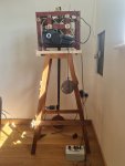
Ok so here is my test clock, collected this morning, you can see the actuator to grab the pendulum located bottom right it works just fine if connected direct to 12 volts and the polarity reversed, need to sort 2 relays to do that function and take it from there
 

Attachments

Top