28x M/C Gear shift indicator

duke12

New Member
I have been trying for some time to perfect a motorcycle gear shift indicator
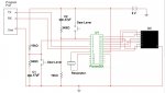
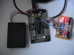
I am driving a 7 segment led with a Pixaxe 28x on a proto board.
Photo:
Gear Indicator2.jpg

Program:
Code:
'2013 fifth version of m/c gear shift indicator
'Set Editor Program to Options Picaxe 28x
'Leverup is switch going low to high on Pin Analog 0 Pin 2 of chip
'Leverdown is switch high going low on Pin Analog 1 pin 2 of chip use striped wire
'work to do !!!!!!!!!!!!!!!!!!!!! 'need to take neutral out of loop out and have it switch by Analog 3 from neutral light or 'neutral switch
 
symbol gearposn = b1:symbol geardisplay = b2:symbol leverdown = b3:symbol leverup = b4  'assign variables b1 (byte1 =8 bits) to b4
'----------------------------------------------------------------------------
gearposn = 1 	 'start in gearposn 0 gear neutral?
pins = $01   	 'show no gear as a default display DotPoint
'---------------=================0000000000000000000000==================------------------------
Start:
							       ' could be both set to read high or low volts
	readadc 0,leverup: if leverup > 150 then upshift 'if low to high volts they pushed the down switch or lever
	readadc 1,leverdown: if leverdown < 150 then downshift 'if high to low volts they pushed the up switch or lever
'debug
goto Start 
end 
'---------------=================0000000000000000000000==================------------------------
upshift: 	'UP COUNTER
	if gearposn = 7 then Start
	gearposn = gearposn + 1  	' move up a gear NOTE starts at 2 above 1st or neutral
	'____________________ display the gear selected!____________________________________________
	'	 gearposn     0    1   2    3    4    5    6    7  DATA counts from 0 up
	'showgear:         '0    1   2    3    4    5    6    7
	lookup gearposn, ( $BE, $82, $DC, $D6, $E2, $76, $7E, $92), geardisplay: pins = geardisplay
	
	wait_up_lever:			'in case they are resting on the switch or lever
	readadc 0,leverup: pause 2
	if leverup > 150 then wait_up_lever
	goto start
'---------------=================0000000000000000000000==================------------------------
downshift:	'DOWN COUNTER
	if gearposn < 1 then Start 
	gearposn = gearposn - 1  		' move down a gear
	'____________________ display the gear selected!____________________________________________
	'	 gearposn    0    1    2    3    4    5    6    7    8		
	'showgear:         '1   2    3    4    5    6    7
	lookup gearposn, ($82, $DC, $D6, $E2, $76, $7E, $92), geardisplay: pins = geardisplay

	wait_down_lever:			'in case they are resting on the switch or lever'
	readadc 1,leverdown: pause 2
	if leverdown < 150 then wait_down_lever
	goto start
'-------------------------------------------------------------------------------------------------


All works ok and I am about to program in the neutral light switch to indicate"0" on the display.


But before that I have a problem with the counter cct or program.
If you look on the accompanying picture you will see I am using two micro switches with component debounce buffered attached. One switch transitions High to low and the other Low to High as can be seen from the programming. Later I intend to replace theses switches with Hall Effect transistors and have both switch low to high.

Problem is:
Counter starts at DP (Dot Point) and counts and displays correctly to the extent of 7 or 1 in either direction without fail.
If I hold one of the switches down the counter waits until I release it before restarting the count as it should.
BUT

1. If i change direction of the counter it takes two -2 presses of the switch to reverse the direction of the count - in either direction.

2. It also take two presses to get off the bottom ie 1 or off the top ie 7.
All other counting and displaying takes the correct one switch action in either direction.

Any Ideas?
Duke
 

inglewoodpete

Senior Member
Welcome to the PICAXE forum.

I have had a look at your code and can't see any standout errors. Please post a circuit diagram of the sensor/switches "component debounce" circuit. A scan/photo of a hand-drawn diagram is usually good enough.

You may need to add some diagnostic code to help get to the bottom of the problem. Eg, Rather than jump immediately after you read the ADCs, first set a bit flag to record the fact so that you can conditionally log data to the Terminal window via the SerTxd command.

Peter
 

inglewoodpete

Senior Member
I'll expand on using bit flags later. In the meantime, you don't show the mandatory resistors on the programming pin (22k + 10k) or the pullup (typically 4.7k) on the reset pin. Without these in place at all times, the PICAXE will behave unpredictably.
 

hippy

Technical Support
Staff member
I would guess the problem is in the LOOKUP commands. The data in the LOOKUP should be the same in both upshift and downshift. Use a single LOOKUP and display routine for what 'gearposn' is and that will help.

gearposn = 1 'start in gearposn 0 gear neutral?
Use gearposn = 0 for neutral and things will be much easier.
 

MartinM57

Moderator
In the meantime, you don't show the mandatory resistors on the programming pin (22k + 10k) or the pullup (typically 4.7k) on the reset pin. Without these in place at all times, the PICAXE will behave unpredictably.
That grabbed me first as well, but as the photo shows, the PICAXE is on a Rev-Ed protoboard, so they can be assumed to be in place - worth checking though
 

duke12

New Member
Yes it is a rev Ed proto board and all necessary programming and pullup components are soldered on board when i got it. There is an electro and two small power supply cap filtering the DC
The IC is acting perfectly in all other experiments. I am just having a problem with the double switch click as described above?

I had a routine with 0 as neutral before this edit - the problem was the same

This ver also had a single lookup and display as "hippy" suggested same problem existed then.
this was the code for that ver.
Code:
symbol gearposn = b1:symbol geardisplay = b2:symbol leverdown = b3:symbol leverup = b4  'assign variables b1 (byte1 =8 bits) to b4
'----------------------------------------------------------------------------
gearposn = 0 	 'start in gearposn 0 gear neutral?
pins = $BE   	 'show 1st gear as a default
'---------------=================0000000000000000000000==================------------------------
Start:
	
	readadc 1,leverdown: if leverdown < 150 then downshift  		'if low volts they pushed the up switch or lever
								' could be both set to read high or low volts
	readadc 0,leverup: if leverup > 159 then upshift    			 'if high volts they pushed the down switch or lever
	
'debug
goto Start 

end

'---------------=================0000000000000000000000==================------------------------
downshift:			'DOWN COUNTER
if gearposn = 0 then inneutrallower
gearposn = gearposn - 1  		' move down a gear
if gearposn < 1 then lockdown  	 'no gear below 1st

wait_down_lever:			'in case they are resting on the switch or lever
readadc 0,leverdown
if leverup > 250 then wait_down_lever
goto showgear

inneutrallower:
gearposn = 2  			'show neutral
goto showgear

lockdown:
gearposn = 1
goto start
'============================================================================================

'---------------=================0000000000000000000000==================------------------------
upshift:				'UP COUNTER
	if gearposn = 0 then inneutralupper
	gearposn = gearposn + 1  	' move up a gear
	if gearposn = 9 then lockup 	 'gear 7 is the highest in this gearbox!
	goto showgear
	
wait_up_lever:			'in case they are resting on the switch or lever
	readadc 0,leverup: pause 100
	if leverup > 150 then wait_up_lever
	goto start
  
inneutralupper:
	gearposn = 2		 'display of neutral
	goto start

lockup:
	gearposn = 8:goto start

'==================================================================================================
'____________________ display the gear selected!____________________________________________
	'	gearposn    0     1    2   3    4    5    6    7    8		
	showgear:        ' 0    1    0    2    3    4    5    6    7
	lookup gearposn, ($BE, $82, $BE, $DC, $D6, $E2, $76, $7E, $92), geardisplay: pins = geardisplay
	return'___________________________________________________________________________________________

Since using the newer ver 1st posted and If I use the line with the debug not remmed out I get this happening on the debug screen while still attached:

the gearposn variable does increment or decrement on each switch movement but
the geardisplay variable noes not change until the second click happens?
This only happens as described above not on straight counting

Problem still exists.
Thanks for your input!
Duke
 
Last edited:

hippy

Technical Support
Staff member
gearposn = 0 'start in gearposn 0 gear neutral?
pins = $BE 'show 1st gear as a default
upshift: 'UP COUNTER
if gearposn = 0 then inneutralupper

inneutralupper:
gearposn = 2 'display of neutral
if gearposn = 9 then lockup 'gear 7 is the highest in this gearbox!

lockup:
gearposn = 8:goto start
I'm completely confused as to how gear selected is represented or why the code is so convoluted.

One problem however seems to be that you have a RETURN in your 'showgear' routine but are not using a GOSUB to get there.
 

westaust55

Moderator
From the earlier photo it seems you are using the AXE022 proto board.
PortA is analogue inputs therein for X1 parts and do not have pull down resistors. So unless you have fitted resistors the inputs float when the switches are open.

It also begs the question why you are using analog inputs rather than say the digital (on/off == high low) inputs a aila LE on PortC?
 

duke12

New Member
Hippy the "return" was just a try to fix that version, I know it fails along with the single sub for "showgear" that didn't help either. I was just showing I had been down that path. The code at the top of this post is the current attempt. I know the older code was a bit of a mess, I hope you see I was trying to make the code "less convoluted" in the final version on the top of the post.
I am a communication electronics technician but only hobbyist coder so please try to bear with my "convoluted" code or a clearer suggestion would be helpful thanks.

I tried digital inputs i.e. on/off, could not get that to work and if I ever get this built in the real world the Hall effect transistors on the gearshift might not be so clearly on/off so I chose to go with a rising - falling voltage.

rosso I will try to recode today using your suggestion to move 'showgear' to the start of the main loop.

Damn thing works perfectly counting up and down - just one bug to fix. Would you believe I have been at this on and off for a year.. ha ha grrr

thanks guys
Duke
 

duke12

New Member
Finally got it working, BIG thanks to Rossko57. I moved the 'showgear code to the start of the main loop as suggested and all is well albeit that it switches on the release of the switch other than the make of the switch but I think I can now construct the hardware from here.
Finished code is here, I think?
Code:
'2013 fifth version of m/c gear shift indicator
'Set Editor Program to Options Picaxe 28x
'Leverup is switch going low to high on Pin Analog 0 Pin 2 of chip
'Leverdown is switch high going low on Pin Analog 1 pin 2 of chip use striped wire
'work to do !!!!!!!!!!!!!!!!!!!!!
'need to take neutral out of loop out and have it switch by Analog 3 from neutral light or neutral switch
'assign variables b1 (byte1 =8 bits) to b4
symbol gearposn = b1:symbol geardisplay = b2
symbol leverdown = b3:symbol leverup = b4: symbol neutral = b5  
'----------------------------------------------------------------------------
gearposn = 0 	 'start in gearposn 0 gear neutral?
'pins = $BA   	 'show NEUTRAL N later when switch by neutral light later
'---------------=================0000000000000000000000==================------------------------
Start:
	'___________________ display the gear selected!____________________________________________
	'	 gearposn    0    1    2    3    4    5    6		
	'showgear:         '0    1   2    3    4    5    6
	lookup gearposn, ($BA, $82, $DC, $D6, $E2, $76, $7E), geardisplay
	pins = geardisplay
							       ' could be both set to read high or low volts
	readadc 0,leverup: if leverup > 150 then upshift 'if low to high volts they pushed the down switch or lever
	readadc 1,leverdown: if leverdown < 150 then downshift 'if high to low volts they pushed the up switch or lever
	goto Start 
end

'---------------=================0000000000000000000000==================------------------------
upshift:				'UP COUNTER
	gearposn = gearposn + 1  	' move up a gear unless at 6
	if gearposn > 6 then
		gearposn = 6
	endif

wait_up_lever:			'in case they are resting on the switch or lever
	readadc 0,leverup: pause 20
		if leverup > 150 then wait_up_lever
	goto start

'---------------=================0000000000000000000000==================------------------------
downshift:			'DOWN COUNTER
	gearposn = gearposn - 1  		' move down a gear unless at 1
	if gearposn < 1 then
		gearposn = 1
	endif
wait_down_lever:			'in case they are resting on the switch or lever'
	readadc 1,leverdown: pause 20
		if leverdown < 150 then wait_down_lever	
	goto start
Working great!
Thanks all
Duke
 

inglewoodpete

Senior Member
A late suggestion: PICAXE has some nifty commands when you need to restrict values to a range.

You can replace
Code:
    gearposn = gearposn + 1  	' move up a gear unless at 6
    if gearposn > 6 then
        gearposn = 6
    endif
with
Code:
    gearposn = gearposn + 1 Max 6    ' move up a gear unless at 6
and....
Code:
    gearposn = gearposn - 1  	' move down a gear unless at 1
    if gearposn < 1 then
        gearposn = 1
    endif
with
Code:
    gearposn = gearposn Min 1 - 1    ' move down a gear unless at 0
 

hippy

Technical Support
Staff member
I moved the 'showgear code to the start of the main loop as suggested and all is well albeit that it switches on the release of the switch other than the make of the switch
You can take that ShowGear code and put it at the end of the program terminated with a RETURN.

Then add 'GOSUB ShowGear' commands -

before the 'start' label
before the 'wait_up_lever:' label
before the 'wait_down_lever:' label
 

Captain Haddock

Senior Member
I know it's totally defeatist from a picaxe point of view but I made an indicator for my FZS600 by buying a secondhand neutral switch for £6 off ebay and drilled extra contacts in using brass braising rod pushed through slightly undersize holes, with a second hand switch the drilling positions are clearly marked for you by natural wear patterns, makes it foolproof.
Worth a thought.
 

duke12

New Member
Captain Haddock I have seen that on the net, with the drilled holes etc. Not sure how to access that but I get your point. Pity I don't have a "Zook" as they have a fully switched output for each gear supplied, "killerzakis" do too I think, but I'm sticking with the Triumph so I have to work around that.

Thanks Hippy that should work but I kinda like the look of it now and it is working well. I might give it a go anyway to see if it reverses the break of the switch to the make which would be good - it just seems like a lot of "calls" to the sub.

Inglewoodpete, "Min" and "Max" - I love it - that is a great command I will use that thanks, trims it down even more.

I am into the hardware now and want to make a mock up on the bench with a lever etc.
I have a Hall Effect transistor UGN3503 but it only varies +/- 1Volt either side of 2.1 volts making the coding a little bit more difficult. also I note this trans has voltage changes with heat which could be a problem on my motorcycle (Triumph Sprint ST)

I found on the net a Hall effect SWITCH which is zero volts with no magnet present - rising to the supply voltage when the magnet is close by, maybe a better sensor. I got a couple of these of the 'bay to try
A3213 Hall Effect Sensor (PIC/Arduino/AVR + AU Stock) 0v to max volts sounds good.

Eventually I would like to have this drive a larger than normal 7Segment as they are available now. I have seen 7Segments up to 2" just like the rally cars have - that is what I would like, right up the front of the fairing. I know that's more current etc but when the bike is off I will power down the cct.

Any thoughts?
Duke
 

PaulRB

Senior Member
Duke, when shopping for large led displays watch out for the Vff figure. If the circuit is running at 5V, you dont want Vff much more than 4V. Many larger blue, white, maybe even green have Vff of more than 6V. As for the extra current, a few transistors may be needed, or a darlington array chip.

Have you thought about the brightness of the display? Bright enough to see in sunshine will be blinding and very distracting at night. You may need an ldr connected to an adc input and a pwm output to drive the common anode or cathode of the display (via a transistor). This will allow your program to read the light level every now and again and adjust the brightness of the display.

Paul
 
Last edited:

inglewoodpete

Senior Member
Eventually I would like to have this drive a larger than normal 7Segment as they are available now. I have seen 7Segments up to 2" just like the rally cars have - that is what I would like, right up the front of the fairing. I know that's more current etc but when the bike is off I will power down the cct.
There certainly are large 7-segment displays. My local electronics supplier has these 70mm displays but they're on the wrong side of the world for you! As Paul points out, note how many LEDs are stacked for each segment. A ULN2803 can be used as a buffer/driver/voltage converter.
 

smeagol

Member
Just a thought. Most bikes seem to blip the neutral light as you go through 1-2 and 2-1.

Might need to be aware of that when adapting to use neutral light as it might upset the counter.
 

hippy

Technical Support
Staff member
Thanks Hippy that should work but I kinda like the look of it now and it is working well. I might give it a go anyway to see if it reverses the break of the switch to the make which would be good - it just seems like a lot of "calls" to the sub.
In putting GOSUB commands where they are needed to do the job required neither doing that, nor the quantity, should be a real problem and if it also avoids convoluted code to make it otherwise work or requiring other changes to achieve the desired result it's a simple 'win'.

If you are happy with how it now works then that is fine but, if you want it to change the display when the gear lever is activated rather than released, I would recommend the GOSUB route rather than altering the hardware operation which may bring with it other issues you have to then resolve.
 

PaulRB

Senior Member
There certainly are large 7-segment displays. My local electronics supplier has these 70mm displays but they're on the wrong side of the world for you! As Paul points out, note how many LEDs are stacked for each segment. A ULN2803 can be used as a buffer/driver/voltage converter.
Pete's example is a case in point: the page does not tell you what the Vff is (or even the colour) but its going to be at least 8 or 9V. Also its common cathode. For use with the uln2803 you would want common anode, am I right Pete?

How about this:http://www.ebay.co.uk/itm/1inch-7segment-RED-LED-display-common-anode-5pcs-LG10016BH-4-5V-/380599153594?pt=LH_DefaultDomain_0&hash=item589d7a33ba
 
Last edited:

duke12

New Member
Ingelwoodpete

Your Min/Max code works on the up shift from the default N position.
But on startup sitting at N will not shift down into 1 or 1st pos?
tried:
"gearposn = gearposn - 1 Min 1"
That made it worse! Hmm
Duke
 

duke12

New Member
Hi Hippy,
I have implemented the code change you suggested thus>
Code:
symbol gearposn = b1:symbol geardisplay = b2
symbol leverdown = b3:symbol leverup = b4: symbol neutral = b5  
'----------------------------------------------------------------------------
gearposn = 0 	 'start in gearposn 0 gear neutral?

'---------------=================0000000000000000000000==================------------------------
gosub showgear
Start:
	readadc 0,leverup: if leverup > 150 then upshift 'if low to high volts they pushed the down switch or lever
	readadc 1,leverdown: if leverdown < 150 then downshift 'if high to low volts they pushed the up switch or lever
	goto Start 
end

'---------------=================0000000000000000000000==================------------------------
upshift:				'UP COUNTER
	gearposn = gearposn + 1  	' move up a gear unless at 6
	if gearposn > 6 then
		gearposn = 6
	endif
	gosub showgear
wait_up_lever:			'in case they are resting on the switch or lever
	readadc 0,leverup: pause 20
		if leverup > 150 then wait_up_lever
	goto start

'---------------=================0000000000000000000000==================------------------------
downshift:			'DOWN COUNTER
	gearposn = gearposn - 1  		' move down a gear unless at 1
	if gearposn < 1 then
		gearposn = 1
	endif
	gosub showgear
wait_down_lever:			'in case they are resting on the switch or lever'
	readadc 1,leverdown: pause 20
		if leverdown < 150 then wait_down_lever	
	goto start
'---------------------------------------------------------------------------------------------------
showgear:
	'___________________ display the gear selected!____________________________________________
	'	 gearposn    0    1    2    3    4    5    6		
	'showgear:         '0    1   2    3    4    5    6
	lookup gearposn, ($BA, $82, $DC, $D6, $E2, $76, $7E), geardisplay
	pins = geardisplay
return
It works now on the 'make of the switch as you said and that is good as I want the indicator to move with the gear lever.
There is an odd problem when I start the program and the display is sitting in the neutral or "N" display. When I sown lever from that position I get no number one. If I go up the counter and back to 1 that works up and down correctly from then. Just a hitch at the start?
Duke
 

duke12

New Member
This is crazy
The + 1 Max 6 works to count upwards but not the -1 min 1>
Code:
downshift:			'DOWN COUNTER
	gearposn = gearposn - 1 min 1
the -1 min 1 code - If I simulate it in step mode the first time the program enters this line it sets the gearposition variable to 255 ??

I tried the syntax using min a inglewoodpete suggested but the same error occurs.
If I step up only and return to one all works ok. I cont seem to be able to go from start program to step down.
This seems a simple up down counting routine but I must be missing a small bit somewhere as it is still wrong.
 

inglewoodpete

Senior Member
Duke, the code you have in post #25 will not work.

As you probably know, PICAXE maths currently works strictly left-to-right. (Until we get PE Vers.6). If gearposn is 0, then gearposn - 1 = 255. Since 255 > 1, the 'Min' operator has no effect.

The correct code is gearposn = gearposn Min 1 - 1. Ie If gearposn = 0, then first change it to 1 before decrementing it to 0, otherwise just decrement it. Hope that makes sense.
 

duke12

New Member
inglewoodpete

I understand the logic, I have been coding for too long in Qbasic and Basic, I get your point.
Would have never guessed that 0 - 1 = 255 !! Kind of screwy logic like dividing by zero.
Anyway...
I put your line in and it almost worked but I kept getting N below 1st
SOooo I changed the line to>
gearposn = gearposn Min 2 - 1

The thing is perfect now. It starts in N and can decrement to 1 and count up and down cleanly without showing the N again - perfect!
I will be switching the Neutral indicator with a +ve from the neutral light on the dash panel using readadc 2, neutral. I will show the N position without changing the count because as mentioned before a bike can show or even be in a "false" neutral between gears.

Now I will make some hardware I guess. I have ordered two Hall Effect "Switches" which output 0volts until a magnet is present then the output rises to +ve batt. I will have to adjust the code accordingly as readadc 1 and 2 will be looking for rising volts. A3213 Hall Effect Sensors.

I like the size of "PaulRB"s larger 7segment led and I agree it will need a LDR to tame it down at night. I will use a separate power supply for the bigger Leds

Thanks Duke.
 

inglewoodpete

Senior Member
Would have never guessed that 0 - 1 = 255 !! Kind of screwy logic like dividing by zero.
I'm glad you've got your code doing what you want.

The PICAXE uses 8- and 16-bit unsigned integers. There is no warning when a number "rolls over" or "rolls under" the limits of the register that it is strord in. These constraints are described in Manual 2.
 

PaulRB

Senior Member
With a separate power supply you will have a much wider choice of even larger sizes and colours. What voltage is the bike's battery?
 

duke12

New Member
PaulRB
The bike is a 07 Triumph Sprint ST 1050 - Sprints have been imported into Australia at about 150 units a year. Uses 12V DC regulated and I have a wiring diagram of the bike. They are built down the road from you at Hinkley.

Thanks 'pete all good now.
Duke
 

PaulRB

Senior Member
12V regulated? Are you sure its regulated?

If so, you can choose almost any display you want. But the voltage and current is likely to be more than picaxe can handle, so I would suggest getting a common anode display, a uln2803 to drive the cathodes and a bc327 pnp transistor to drive the anode. You can use the 8th darlington in the uln to drive the pnp base through a resistor. Maybe you already know this stuff, in which case apologies.

Paul
 

duke12

New Member
Paul,

Thanks for your input. Yes the power from the alternator is rectified and smoothed to very clean DC from their ctt diags, so I am sure it will be good. I will have a look at the display driver you mentioned. The 12v could easily be clamped down to the Picaxe requirement using the ccts from the Picaxe manual.

I have a Multisim Electronics Simulator so I can mock all of the driving ccts and experiment to my hearts content before I make some real life hardware. Bit of a pain Multisim has a lot of PICs listed in their library but not the equivalent for the 28x = PIC16F873A so that may be a problem for simulating but I may be able to create sim a "Block" for that bit.

Apologies are never necessary If a person stops listening, taking advice or learning then they have stopped period.
Duke
 

ROGER555

New Member
Hey Duke I just stumbled accross your project while researching a similar project. I would like to build a gear position indicator for my 6-spd manual car. After reading through your thread I don't think your program would work well for my application as it seems shifting a motorcycle is only linear up and down?? Can you skip shift with a motorcycle or shift into neutral from any gear?

My initial though was to mount 6 HALL switches around the shifter, each switch once activated could switch the number to the indicated gear. The only concern is possible problems caused by the proximity of the HALL switches.

Any thoughts/ suggestions for myapplication? hopefully its something I can program in logicator because I don't know how to code :(


Hi Hippy,
I have implemented the code change you suggested thus>
Code:
symbol gearposn = b1:symbol geardisplay = b2
symbol leverdown = b3:symbol leverup = b4: symbol neutral = b5  
'----------------------------------------------------------------------------
gearposn = 0 	 'start in gearposn 0 gear neutral?

'---------------=================0000000000000000000000==================------------------------
gosub showgear
Start:
	readadc 0,leverup: if leverup > 150 then upshift 'if low to high volts they pushed the down switch or lever
	readadc 1,leverdown: if leverdown < 150 then downshift 'if high to low volts they pushed the up switch or lever
	goto Start 
end

'---------------=================0000000000000000000000==================------------------------
upshift:				'UP COUNTER
	gearposn = gearposn + 1  	' move up a gear unless at 6
	if gearposn > 6 then
		gearposn = 6
	endif
	gosub showgear
wait_up_lever:			'in case they are resting on the switch or lever
	readadc 0,leverup: pause 20
		if leverup > 150 then wait_up_lever
	goto start

'---------------=================0000000000000000000000==================------------------------
downshift:			'DOWN COUNTER
	gearposn = gearposn - 1  		' move down a gear unless at 1
	if gearposn < 1 then
		gearposn = 1
	endif
	gosub showgear
wait_down_lever:			'in case they are resting on the switch or lever'
	readadc 1,leverdown: pause 20
		if leverdown < 150 then wait_down_lever	
	goto start
'---------------------------------------------------------------------------------------------------
showgear:
	'___________________ display the gear selected!____________________________________________
	'	 gearposn    0    1    2    3    4    5    6		
	'showgear:         '0    1   2    3    4    5    6
	lookup gearposn, ($BA, $82, $DC, $D6, $E2, $76, $7E), geardisplay
	pins = geardisplay
return
It works now on the 'make of the switch as you said and that is good as I want the indicator to move with the gear lever.
There is an odd problem when I start the program and the display is sitting in the neutral or "N" display. When I sown lever from that position I get no number one. If I go up the counter and back to 1 that works up and down correctly from then. Just a hitch at the start?
Duke
 

boriz

Senior Member
...I would like to build a gear position indicator for my 6-spd manual car...hopefully its something I can program in logicator because I don't know how to code :(
That's a bit like saying I'd like to grow my own apples, but I only have a window box.
 

ROGER555

New Member
That's a bit like saying I'd like to grow my own apples, but I only have a window box.
Well not a very good analogy, I have built several circuits programming with logitcator. I think you forgot the PICAXE geared toward people like me.
 

boriz

Senior Member
...I think you forgot the PICAXE geared toward people like me.
Not at all. My comments were about Logicator, not about Picaxe, as I'm sure you know.

I'm not saying it's impossible, just that you're handicapping yourself from the outset. Like trying to grow apples in a window box. Not impossible, but much harder than it need be. There are many things a window box is ideally suited for, but growing apples isn't one of them. I consider Logicator similarly.

Firstly, you are limited by what logicator can do. Secondly, you will find relatively few of the experienced contributors on this forum (the very people whose help you need) use logicatior and are able to help in any specific way. Thirdly, trying to 'write' anything in the least bit complicated using flowcharting is going to be more trouble than it's worth. I'm sure I've said it before, flowcharts are ok for organizing your thoughts, and have an educational role to play in the introduction of logical 'programming like' thinking, but almost useless as a real programming 'language'.
 
Last edited:
Top