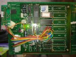
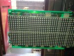
I have inherited a pre-built Large 240 x 16 LED matrix - separated into 3 sub-units cascaded together, the sub-units are then made up of 8x5 LED matrix.
I know something is working as the display shows the welcome screen on startup. From what I can gather, I can load data into the control unit's eeprom and send it control signals to update the display
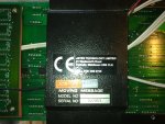
All attempts via software and serial port have been fruitless except I've managed to register a DSR signal on the serial port. The manufacturers website is a no go, as they won't give me the software without me being one of their engineers.
Anyone ever tried anything like this? I've read some posts that people have made their own and if it comes to it I will have to take it apart and rebuild it, I would just like to see if I can get it working before I switch to picaxe.
The end result I'm after is displaying alphanumeric characters, no fancy scrolling/flashing/animation at all.
A pointing finger or gentle push in the right direction would be gratefully received.
I know something is working as the display shows the welcome screen on startup. From what I can gather, I can load data into the control unit's eeprom and send it control signals to update the display
All attempts via software and serial port have been fruitless except I've managed to register a DSR signal on the serial port. The manufacturers website is a no go, as they won't give me the software without me being one of their engineers.
Anyone ever tried anything like this? I've read some posts that people have made their own and if it comes to it I will have to take it apart and rebuild it, I would just like to see if I can get it working before I switch to picaxe.
The end result I'm after is displaying alphanumeric characters, no fancy scrolling/flashing/animation at all.
A pointing finger or gentle push in the right direction would be gratefully received.
")