20X2, SPI and Voice Chip

ccdubs

Member
Hi All,

I would like to use a 20X2 chip to control a voice record and playback chip, specifically an ISD15100 via SPI. Being a novice with communications I was hoping for some clarity before I delve into detail.

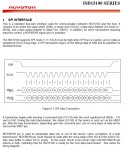
As I understand it, when I send a command byte to the ISD15100, during the transmission the status of the ISD is returned via the MISO pin (each command bit on the MOSI line triggers a bit on the MISO line representing status of different parameters). Will the built in SPI functions of the 20X2 allow me to read this chip status while also sending?

The ISD chip also states it uses SPI mode 3 but I can't figure out how this applies to the HSPISETUP mode variable.

Any help is greatly apprectiated.
 
Last edited:

westaust55

Moderator
By the lack of response thus far, I suggest few, if any regulars have used the chip you mention.

Do you have just the chip, is it on a breakout board or is it as part of some module with a “front end”

A link to the device datasheet and any other information that YOU already have found might encourage others to delve on your behalf.
 

ccdubs

Member
Thanks for the advice. The chip is standalone and I will be integrating it into a circuit of our own design. I have attached an image of the relevant page in the user manual, which shows how S7-S0 are sent at the same time that C7-C0 are received.

After consideration being to able to read S7-S0 is not compulsary as i can get the same information with a standard data request transmission. However, I would still like to know if this is doable.

More importantly if someone could tell me what HPISETUP configuration is equivalent to SPI mode 3, I would really appreciate it.
 

Attachments

hippy

Technical Support
Staff member
Based upon http://en.wikipedia.org/wiki/Serial_peripheral_interface

"SPI Mode N" (0-3) is equivalent to "SPI Mode (N.1,N.0)" when the two bits of 'N' are split out. The left bit is the polarity (CPOL), the right bit is the phase (CPHA).

At CPOL=0 the base value of the clock is zero
- For CPHA=0, data is captured on the clock's rising edge (low→high transition) and data is propagated on a falling edge (high→low clock transition).
- For CPHA=1, data is captured on the clock's falling edge and data is propagated on a rising edge.

At CPOL=1 the base value of the clock is one (inversion of CPOL=0)
- For CPHA=0, data is captured on clock's falling edge and data is propagated on a rising edge.
- For CPHA=1, data is captured on clock's rising edge and data is propagated on a falling edge.

On the PICmicro CPOL -> CKP and CPHA -> CKE, plus an additional SMP which indicates where sampling occurs. As best as I can tell ...

Mode 0 -> Mode(0,0) -> CKP=0 CKE=0 SMP=0 -> spimode00
Mode 1 -> Mode(0,1) -> CKP=0 CKE=1 SMP=0 -> spimode01
Mode 2 -> Mode(1,0) -> CKP=1 CKE=0 SMP=1 -> spimode10e
Mode 3 -> Mode(1,1) -> CKP=1 CKE=1 SMP=1 -> spimode11e
 
Top