Andrew Cowan
Senior Member
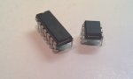
Running out of code space on a 14M, and not having space for a larger chip, I've taken Dave E's idea and converted a 20X2 into a 14X2.
Works perfectly!
Andrew
Works perfectly!
Andrew
Attachments
-
 582.9 KB Views: 161
 .
.