2 Questions-Variable resistors and LEDs

I am in the process of making a fairly complex system, and have just a couple of queries.

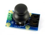
Firstly, I need two variable resistors to make a small joystick, such as on a PS2 controller. I do not know where I can find one of these with springs in, so if anyone knows, it would be helpful. My query regarding using picaxe is the code I must use to interpret the position of the Variable Resistors, to control the direction and speed of the output (2 stepper motors driven by the chips L293D)

My second section that I am stuck on is how I can integrate LEDs into a matrix of buttons, a little like in the keypad project. I have six PTM switchs on 2 outputs and 3 inputs, and when a button is pressed, I want a corresponding LED to come on. When another button is pressed, that LED must go off and another must come on. I do not have any spare outputs on the picaxe chip (18X) and do not want to go any bigger unless absoloutley necessary.
The only solution that I can think of is to have 2 PTMs linked together (mechanically, not electrically); one for the input to the picaxe, and the other to power the LED, linked into a bistable decive such as a thyristor. I am not sure how to turn the LED off however.

Any ideas?
 

BeanieBots

Moderator
You should be able to get a joystick from one of the many radio control hobby stores. They're not cheap though. The pots are designed for frequent use and cost more than your average volume control pot.
Reading it is easy. Have a look at the command ReadADC.
The value will be between 0 and 255 with 128 when in the middle.
If you test and then remove the MSB (128) you can use that for direction and the remainder for speed demand.

Not sure what you can do about the LED problem without using extra hardware such as an IO expander.
 

jonphenry

New Member
Are the LEDs to stay on after releasing the button or only be on while it is pressed?

I assume one LED for each button, so six LEDs?

What exactly are you trying to control?
 
Yes, once a button has been pressed, the LED must remain on. When a different button is pressed, the first LED must switch off, and the new LED must switch on.
Although I will have 6 buttons (AUTO, CENTRE, Program1, Program2, Program 3, and Record), only 4 of them need LEDs.
The system will be a camera control unit, wirelessly linked to a camera.

PS, I have just taken a joystick out of a PS2 controller, although I found a site www.apem.co.uk which I think allows for free samples.
 

jonphenry

New Member
Are you using an off the shelf keypad or is it custom?

If its custom, take a look at my site at the ADC keypad concept. It uses 1 ADC input to read multiple buttons. We physically tested it out to 20 switches successfully. Using 6 would be very very easy. This would free up the outputs saved from the traditional keypad concept to use for LEDs.
 

craig008

New Member
i have a busted up ps3 controller, PM me if you want the internals for ur project

i would do similar to computers so it the stick is moved to postion 150 that would translate into forward slow and 256 foward fast and 0 backward fast, the biggest problem that i am having troubles with is how to get the higher number to have a smaller pause between commands - i imagined a programme like this is if if is any help

main:
readadc verticle
readadc horisontal
send to stepper motor
pause vertical
pause horisontal
goto main

i am not sure what ot do about the LEDs, i remember one thing my IT teacher said to me KISS - keep is simmpple stupid (this is not meant as an insult by the way) so maybe the leds should just come on when the botton is pressed, that way it can be linkes in with the botton circuit and keeping the whole thing simple, after that the simplest way is to increase chip size but as you said you do not want to do that
________
Herbal Vaporizers
 
Last edited:
I have been looking at alternatives for the LEDs, but think I may have none, since there is nothing simpler than that!
I have been looking at ways to implement the joystick, including speed, and although it is long and in its early stages (can probably be simplified), I have come up with this:
Code:
init:
b9=45
b8=45
b11=0
main:
readadc 1, b7
b11=0
select b7
	case 0 to 30
		b11=1
		if b9>=4 then
			b9=b9-4
		else
			b9=0
		endif
	case 31 to 60
		b11=1
		if b9>=3 then
			b9=b9-3
		else
			b9=0
		endif
	case 61 to 90
		b11=1
		if b9>=2 then
			b9=b9-2
		else
			b9=0
		endif
	case 91 to 120
		b11=1
		if b9>=1 then
			b9=b9-1
		else
			b9=0
		endif
	case 121 to 150
		b11=0
	case 151 to 180
		b11=1
		if b9<=89 then
			b9=b9+1
		else
			b9=90
		endif
	case 181 to 210
		b11=1
		if b9<=88 then
			b9=b9+2
		else
			b9=90
		endif
	case 211 to 240
		b11=1
		if b9<=87 then
			b9=b9+3
		else
			b9=90
		endif
	case 241 to 270
		b11=1
		if b9<=86 then
			b9=b9+4
		else
			b9=90
		endif
endselect
readadc 2, b10
select b10
	case 0 to 25
		if b8>=4 then
			b8=b8-4
		else
			b8=0
		endif
		gosub transmit
	case 26 to 50
		if b8>=3 then
			b8=b8-3
		else
			b8=0
		endif
		gosub transmit
	case 51 to 75
		if b8>=2 then
			b8=b8-2
		else
			b8=0
		endif
		gosub transmit
	case 76 to 100
		if b8>=1 then
			b8=b8-1
		else
			b8=0
		endif
		gosub transmit
	case 101 to 125
		if b11=1 then gosub transmit
	case 126 to 150
		if b8<=89 then
			b8=b8+1
		else
			b8=90
		endif
		gosub transmit
	case 151 to 180
		if b8<=88 then
			b8=b8+2
		else
			b8=90
		endif
		gosub transmit
	case 181 to 210
		if b8<=87 then
			b8=b8+3
		else
			b8=90
		endif
		gosub transmit
	case 211 to 260
		if b8<=86 then
			b8=b8+4
		else
			b8=90
		endif
		gosub transmit
endselect
goto main
I then plan to transmit the co-ordinates found in variables b9 and b8 to another chip, which convert the values into 4 outputs, positioning each stepper motor into the required position. I will use a MAX7219 chip in the control unit, displaying the pan and tilt positions of the camera.
 
Top