18x to 8

Hi all

I am on the cusp of getting my RX and TX to field testing. I have decided to run a Picaxe 8 to monitor serin (not sure if you remeber but i need a cancel function to be sent to the RX unit)

I have it working alongside my 18x (which does all the work) I can download programs to each. I want fire up a pin on the 8 (when it receives the right serin data) and read this input on the 18x. The thing is... I connected pin 0 of the 8 to pin 6 of the 18 and wrote the appropriate code to check its state. I think I fried my 8 (well I replaced it and he new one works (but not with the connection between the two chips.) It's been bugging me.

Cheers
 

inglewoodpete

Senior Member
You could well have fried your 08. Its pins are bothway and you may have had both chips with opposite outputs (one output at +5v and the other chip at 0v at the same time).

When interconnecting two chip directly like you are, always put a 330ohm resistor in between the output of one PICAXE and the the input of the other. This will limit any accidental current between the two chips to a safe (ie non-destructive) level.
 
Thanks

I ended up putting a darlington chip between another 18x. Works fine. I can now recieve another serin var and stop the sub running on the main chip. On another issue, is there anyone in Oz who will make a PCB out of a circuit drawing. I've had a go at drawing a PCB but there has to be someone out there who will do a far better job than me.
 

manuka

Senior Member
How involved is your circuit? Budget ? What is this all for ? There are indeed many Oz. PCB designers/makers, BUT often at a serious price for 1 offs -we Kiwis get many PCBs made in China, although full artwork must be supplied. Considered a Kiwi Board (see => www.picaxe.orcon.net.nz) approach?

Perhaps check software packages such as EAGLE, DipTrace, PCB Wizard etc etc (Goggle for more). This PCB need crops up near endlessly on the forum, often with attendant yelling & screaming about the merits & woes of a particular offering. Packages all have significant learning curves... Stan
 
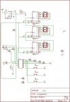
Circuit

I have tried to draw it in the Eagle Soft program. No easy feat, the library function is a bit iffy. This circuit scrolls through some times (Case statements in the code) increments the dec counters, and then sends this data to another unit It also has a cancel funtion hence the three switches. I have tested it and does work, not sure about the drawing though.

Any feed back on my circuit would be nice, I am new at this and it is all self taught.
 

Attachments

eclectic

Moderator
Chris.
A few quick points about your circuit.
I'm using Manual 1 page 25 and Manual 3 page 22.

IC4 (18X)
Leg 1 is INPUT2
Leg 5 connection to GND?

IC3 (4026)
Leg 1 is connected to Picaxe INPUT2
Leg 8 GND?
Leg 16 connection to +5v?

7 segment displays. Do they need resistors?
(I'm not sure on this one, but you might need
to check the output voltage on your 4026).

There may be others?
And I may need new reading specs.

e.
 
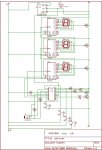
New and Improved Drawing

HI There E

I have gone back and fixed it up and now there seems to be no problems with it. I would like any feedback on the design, as I said I am new to this. Also, if Dr Acula is watching, or anyone who knows anything about Eagle Light(great program, library is a bit of a chore though) , the only problem I have is when I go to greate the PCB drawing, I am having trouble finding a 433 rx unit in the same dimension as my own (Which is 16mm x 16mm - pins 12mm spacing and 8mm spacing) there does not seem to be one like it in the extensive Eagle Library.

Cheers
 

Attachments

Mycroft2152

Senior Member
Chris,

You might consider going with an LCD display. They are much easiesr to use*, a lot less wiring and best of all are readable outdoors in sunlight.

If you must go with LEDs, there are some very cheap 4 digit displays with controllers. I think Spark=un has one.

Myc

*Dippy, I'm suggesting an LCD with a serial interface, not driving it with the 18X.
 

eclectic

Moderator
Chris. I don't know if my cheap specs are playing up, but
on your diagram IC5 (18X)

Leg 1 (input 2) Is there a 10k resistor missing?

Leg 3 (serin). Could you recheck the resistor arrangement (Man 1 p.25)?

Leg 5 0v. I can't see a direct connection to 0v/gnd.

e.
 

hippy

Ex-Staff (retired)
@ Chris : A few comments on your circuit ...

You probably want to connect RF GND on the transmitter.

There are no 100nF decoupling capacitors.

Check the serial programming jack; that's a switched mono socket, not a stereo socket.

A single R for each 7-segment will work but the display will be much dimmer when showing "8" than it will be when showing "1". Ideally use one R per segment, common cathode direct to 0V.
 

moxhamj

New Member
I'll second Mycroft's comments about LCDs. Poor man's version is to have no display and use a lot of 'debug' commands while getting the code working. Or some simple led flashes to indicate various variables.

Eagle's library is really bad - the search hardly works at all. But lots of components are hidden away in strange places - eg 9 pin D connectors are under con-subd. If you have half an hour, just mindlessly scroll through every library and see what is there. And if you do find a useful component, put a comment near it on the schematic as to where it is hidden and then you can find it again later.

Or ask on this forum!

For radio modules, is this a single inline module? If so, use a single inline header of the required number of pins - look in the con-lstb library. If it isn't that, then can you post a picture, maybe with it next to a bit of veroboard so we can see the scale.
 

hippy

Ex-Staff (retired)
Re Eagle : The libraries can be a real pain. It would be really handy if someone proficient with Eagle could consolidate all the commonly used components into a single library ( or library set ) and sensibly indexed with user friendly names so things can be easily and quickly found. Most hobbyists use one type of resistor, one type of 100nF decoupling capacitor, maybe three or four 'industry standard diodes' and so on.

I'm surprised regular Eagle users don't do this anyway. Maybe they do but aren't sharing ?

Any takers ?
 

Mycroft2152

Senior Member
Re Eagle : The libraries can be a real pain. It would be really handy if someone proficient with Eagle could consolidate all the commonly used components into a single library ( or library set ) and sensibly indexed with user friendly names so things can be easily and quickly found. Most hobbyists use one type of resistor, one type of 100nF decoupling capacitor, maybe three or four 'industry standard diodes' and so on.

I'm surprised regular Eagle users don't do this anyway. Maybe they do but aren't sharing ?

Any takers ?
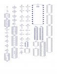
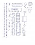
Sorry Hippy, taken and not stirred. For my own convenience, I've been doing just that. Unfortunately for the EAGLE users, it is in DIPTRACE. (Another free pcb program).

If anyone wants a specific component added, send me the details, I'll add it and share the library. for the record, I started this library for making pcbs for BEAM Robots, then added the PICAXE chips to it.

Myc
 

Attachments

Last edited:

hippy

Ex-Staff (retired)
For my own convenience, I've been doing just that. Unfortunately for the EAGLE users, it is in DIPTRACE. (Another free pcb program).
Having had Eagle again lose synch between schematic and board layout ( for the final time ) I've decided to move to Dip Trace. For the small and simple boards I'm interested in and the level I'm at it's easy enough to just use the PCB layout designer. Going from a vero-board prototype anyway it's really just a matter of dropping the component shapes and adding virtual wires then leaving it to auto-route.

Schematic to PCB conversion doesn't work in the demo / under 98SE for me, but I may give it a try under XP.

One question ... what "RES-xx.x/Wxx.x" is a bog-standard 0.25W R ?
 

Mycroft2152

Senior Member
One question ... what "RES-xx.x/Wxx.x" is a bog-standard 0.25W R ?
That is the length and width of the resistor body in mm. The RES-10.7/w7 should work fine. You can do an actual size print out by the print preview button to check. (thats how you would do the artwork for toner transfer or photo method pcbs).

Turn off the grey component outline (it just gets in the way) by

VIEW>Assembly Layers > Pattern Borders

The component outline is grey assuming you have the black background default in VIEW > Colors.

Myc
 
@ Chris : A few comments on your circuit ...

You probably want to connect RF GND on the transmitter.

There are no 100nF decoupling capacitors.

Check the serial programming jack; that's a switched mono socket, not a stereo socket.

A single R for each 7-segment will work but the display will be much dimmer when showing "8" than it will be when showing "1". Ideally use one R per segment, common cathode direct to 0V.
Hi Hippy - thanks for the heads up. Where would I use a decoupling cap and why?
 
Chris,

You might consider going with an LCD display. They are much easiesr to use*, a lot less wiring and best of all are readable outdoors in sunlight.

If you must go with LEDs, there are some very cheap 4 digit displays with controllers. I think Spark=un has one.

Myc

*Dippy, I'm suggesting an LCD with a serial interface, not driving it with the 18X.
Hi M - thanks

I was using a LCD display that I was driving off the 18x, way too hard. Thats why I went with a simple 7 seg. I understand what you are saying, where is Australia would I get a LCD with a serial interface?
 
Re Eagle : The libraries can be a real pain. It would be really handy if someone proficient with Eagle could consolidate all the commonly used components into a single library ( or library set ) and sensibly indexed with user friendly names so things can be easily and quickly found. Most hobbyists use one type of resistor, one type of 100nF decoupling capacitor, maybe three or four 'industry standard diodes' and so on.

I'm surprised regular Eagle users don't do this anyway. Maybe they do but aren't sharing ?

Any takers ?
I am trying that as we speak. I think i will create a .sch file with all of the common componets and then create a library out of it. I tried it last night and it sort of worked.
 

moxhamj

New Member
Mycroft, as an Eagle expert can you please help with a problem replicated on three computers by two different people - the smd-ipc.lbr library does not appear to be available to select components from. Have tried updating the library files etc. This library is a default one including with the program download.
 

Mycroft2152

Senior Member
Hi Doc.

Which version of Diptrace are you using? 1.40 or 1.50 Also what is the version date?

Myc

Note: rather than hijack this thread, I'll start a Diptrace for PICAXE users thread.
 
Top