14M to LCD? How?

DLP1

New Member
I have a 16x2 lcd with a 14m picaxe. In the getting started manual 3 it has a diagram of the different ways you can interface the lcd with the chip. Well every one shows an 18 pin picaxe and it's just not working out for me.

Ive looked all over but all I see listed are 8pin picaxe chips, 18 and I think it was 28. Right now what I have tried is;
LCD PICAXE14M
Pin11 (DB4) - output pin 5
Pin12 (DB5) - output pin 4
Pin13 (DB6) - output Pin 3
Pin14 (DB7) - output pin 2
Pin6 ( E ) - output pin 1
Pin4 ( RS ) - output pin 0

Then
Pins 16 and 1 - 0v
Pins 15 and 2 - +4.5

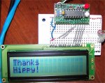
I get 16 box's to light up on the left. The other half stays unlit.
I think all I need right now is the proper wiring. Help?
 

moxhamj

New Member
The reason everyone uses the 18X (and bigger) is that it is hard to fit the code into a 14M. It is possible, but there is hardly any room left for the rest of the program. So from a practical perspective, get an 18X.

Of course, your code can be ported from the 14M to the 18X. Can you post your code. LCD displays are a bit of a black art and once you get it working it is a great feeling.
 

hippy

Technical Support
Staff member
LCD Code for 14M

The attached is untested but should work for a 14M.

When I started to write the LCD drivers it was to make it more readable and maintainable than other versions and to make it maximally optimised. It uses just 52 bytes for the core LCD driver which leaves over 200 bytes for display control and 'real program'. Maintainability proven by the few minutes worth of editing to create an entirely different pinout for the 14M.
 

Attachments

Last edited:

lbenson

Senior Member
>LCD displays are a bit of a black art

And so it always had seemed to me, but inspired by Hippy's code I put an LCD and a JRHackett 14M miniboard on a breadboard, ran 14 wires, plugged in power and programming cable, copied and programmed Hippy's code, and voila!
14LCD_1C.JPG

I replaced the pot with a jumper from 0V to pin3 on the LCD.

Happy camper.
 
Last edited:

AllyCat

Senior Member
Hi,

A very old thread, but as it is still being recommended (for good reason) now in 2021, it's worth noting that hippy's excellent program was written specifically for the 14M PICaxe, since the M2 family of PICaxes had not been released in 2008. However, the program will NOT work with the present 14M2 chips without making a few small changes, in particular because the "M" family had separate dedicated Input and Output Pins. So I have made the necessary changes (and a few refinements) which I'm posting in-line below. Only checked on the Simulator, but hopefully somebody else will comment if I've made any silly mistakes.

To fit the program onto a 14M, hippy had to use the "Serial Output (Programming) Pin" for the RS (Command/Data) line, so I have taken the opportunity to move that onto a portC pin, i.e. C.0, but RS and the E(nable) pins could use almost any "available" pins on most M2 PICaxes. However, hippy has "Hard Coded" the four "Data" pins into the program, which would need some further modifications to use different (14M2) pins, or pins on other PICaxe chips. In particular, a user might want to "free up" the two I2C Data Bus pins (SDA and SCL), which is certainly possible. But it might be better to start with a more recent "Universal" program, for example as described by Westaust55 InglewoodPete HERE.
Code:
#PICAXE 14M2
      SYMBOL  RS     = C.0         ; 0 = Command   1 = Data  ** Moved from SerOut pin
      SYMBOL  E      = B.1         ; 0 = Idle      1 = Active
      SYMBOL  DB4    = B.2         ; LCD Data Line 4
      SYMBOL  DB5    = B.3         ; LCD Data Line 5
      SYMBOL  DB6    = B.4         ; LCD Data Line 6
      SYMBOL  DB7    = B.5         ; LCD Data Line 7
      SYMBOL  getb   = b11
      SYMBOL  bite   = b12

PowerOnReset:
      DIRSB =%111100    			 ; Make the data pins Outputs
      LOW RS    			 		 ; Initialise the pins as (Low) Outputs
      LOW E
      GOSUB InitialiseLcd
DisplayTopLine:
      EEPROM 6,("Hello")
      FOR getb = 6 TO 10
          READ getb,bite
          GOSUB SendDataByte
      NEXT
MoveCursorToStartOfSecondLine:
      bite = $C0
      GOSUB SendCmdByte
DisplayBottomLine:
      EEPROM 11,("World!")
      FOR getb = 11 TO 16
          READ getb,bite
          GOSUB SendDataByte
      NEXT
      END
InitialiseLcd:
      FOR getb = 0 TO 5
          READ getb,bite
          GOSUB SendInitCmdByte
      NEXT
' Nibble commands - To initialise 4-bit mode
      EEPROM 0,( $33 )    ; %0011---- %0011----   8-bit / 8-bit
      EEPROM 1,( $32 )    ; %0011---- %0010----   8-bit / 4-bit
' Byte commands - To configure the LCD
      EEPROM 2,( $28 )    ; %00101000 %001LNF00   Display Format
      EEPROM 3,( $0C )    ; %00001100 %00001DCB   Display On
      EEPROM 4,( $06 )    ; %00000110 %000001IS   Cursor Move
                            ; L : 0 = 4-bit Mode    1 = 8-bit Mode
                            ; N : 0 = 1 Line        1 = 2 Lines
                            ; F : 0 = 5x7 Pixels    1 = N/A
                            ; D : 0 = Display Off   1 = Display On
                            ; C : 0 = Cursor Off    1 = Cursor On
                            ; B : 0 = Cursor Steady 1 = Cursor Flash
                            ; I : 0 = Dec Cursor    1 = Inc Cursor
                            ; S : 0 = Cursor Move   1 = Display Shift
      EEPROM 5,( $01 )      ; Clear Screen
      RETURN
SendInitCmdByte:
      PAUSE 15                        ; Delay 15mS
SendCmdByte:
      LOW RS                       ; Set to Command mode
SendDataByte:
      pinsB = bite / $10 * 4        ; Put MSB out first
      PULSOUT E,1                     ; Give a 10uS pulse on E
      pinsB = bite * 4                ; Put LSB out second
      PULSOUT E,1                     ; Give a 10uS pulse on E
      HIGH RS                       ; Set to Data mode for next use
      RETURN
Cheers, Alan.
 
Last edited:

inglewoodpete

Senior Member
Hi,

A very old thread, but as it is still being recommended (for good reason) now in 2021, it's worth noting that hippy's excellent program was written specifically for the 14M PICaxe, since the M2 family of PICaxes had not been released in 2008. However, the program will NOT work with the present 14M2 chips without making a few small changes, in particular because the "M" family had separate dedicated Input and Output Pins. So I have made the necessary changes (and a few refinements) which I'm posting in-line below. Only checked on the Simulator, but hopefully somebody else will comment if I've made any silly mistakes.

To fit the program onto a 14M, hippy had to use the "Serial Output (Programming) Pin" for the RS (Command/Data) line, so I have taken the opportunity to move that onto a portC pin, i.e. C.0, but RS and the E(nable) pins could use almost any "available" pins on most M2 PICaxes. However, hippy has "Hard Coded" the four "Data" pins into the program, which would need some further modifications to use different (14M2) pins, or pins on other PICaxe chips. In particular, a user might want to "free up" the two I2C Data Bus pins (SDA and SCL), which is certainly possible. But it might be better to start with a more recent "Universal" program, for example as described by Westaust55 HERE.

Cheers, Alan.
Near miss, Alan. InglewoodPete, same city, different Forum Member.
 

AllyCat

Senior Member
Hi,

My apologies, the post is now corrected. I'm quite relieved if that's my only mistake in the post. And as an engineer I'd claim that an error of <10km in 20,000km is "within tolerances" (+/- 0.05%). :)

Cheers, Alan.
 
Top