12V trigger for my Picaxe-controlled preamp utility board

wapo54001

Senior Member
I have put together a pcb that is controlled by a 14M2 and has all of the extra circuitry that I want in my kit-built vacuum tube preamp -- relay-switched in/out, delay, muting, etc. It all works well except it draws rather more current than I would like due to the Rube-Goldberg dual LM317 setup I'm using.

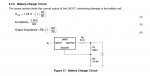
Part of what I want is 12V 25mA power to be the "trigger" to turn on my downstream power amp. Presently I use two LM317s (U3 and U4 in the photo) to first regulate current and then regulate voltage to achieve the 12V 25mA output. It works, but between the two ICs I waste quite a bit of current and I wish I had a better method. I stumbled across the "battery charger" circuit which uses one 317 and three resistors and I understand the general idea but I do not understand what happens when the load asks for more than 12V or 25mA. The brief explanations I have found always say the circuit "protects the battery" but nowhere can I find where it says how it protects the battery, and it claims to provide a low current float charge when the battery is fully charged.

Has anyone used this battery charger circuit? How does it work and is it appropriate for my application? Will it deliver the 12V and 25mA in normal operation and then what happens when the demand exceeds the specification? Voltage drop? Current drop?
 

Attachments

AllyCat

Senior Member
Hi,

Personally, I doubt if that 0.2 ohm resistor does anything useful to "protect" the battery (or anything else). :(

The operation of the circuit is quite simple: the LM317 is designed to deliver as much current as necessary (within reason) from its output pin for it to be 1.25 volts higher than its "Adjust" pin. First, if we assume the output current is quite low (some mA) then there will be no significant voltage drop across Rs, so there must be 1.25 volts across R1. Ohms Law tells us that the current in R1 must be 1.25 / 240 (volts / ohms) or just over 5 mA. Little current flows in the Adjust pin (~50 uA) so the ~ 5mA must flow through R2, giving a voltage drop of about 5 * 2.4 k = 12 volts. Thus the LM317 "regulates" the output (battery) voltage at (10 + 1) * 1.25 = 13.75 volts. If the battery voltage is lower, then more current must flow in Rs (until it drops by whatever voltage is "missing" across R2). Or if the battery voltage is higher then the LM317 will switch off and the battery will slowly discharge via R2.

However, if the battery was actually a "short circuit" then there would need to be 1.25 volts across the 0.2 ohms Rs, or a current of 6.25 Amps ! In practice, the LM317 has an internal current limit of 0.5 - 1 Amps, so it is THAT which will limit the current (or the over-temperature protection may limit the current to an even lower value). With a more "sensible" value of say 10 ohms for Rs, then the (short circuit) current will limit to 1.25 / 10 = 125 mA (or ~12.5 mA with 100 ohms, etc.).

The problem is that this circuit has a simple "linear" regulation characteristic, so if you choose Rs to limit the short circuit current to say 100 mA, then the "regulator" will deliver 50 mA at 6.7 volts or only 10 mA at ~12 volts, etc.. Most regulators have a "dual slope" characteristic, the first giving a substantially constant voltage output (i.e. a low output impedance) and then a current-limiting stage cuts in if the current becomes excessive. That's probably the reason why your present circuit uses two LM317s (one for each slope) and the regulation voltage and current limits could be independently selected by changing the appropriate resistor values. More sophisticated regulators can give a "fold-back" current limit, such that the current actually reduces if the voltage drop across the regulator transistor becomes "unexpectedly" too high (thus limiting the total power dissipation).

Cheers, Alan.
 

wapo54001

Senior Member
The 0.2 ohm Rs is a sample circuit from a TI publication. When I did my numbers I came up with an Rs of 50R to give me 25mA which is my target. I was hoping to use a single regulator to regulate the output to 12V and 25mA as the sustainable voltage and current. I could not understand the interaction between the current regulating Rs and the voltage regulating R1 and R2, and I still don't. And not understanding, I could not tell if this circuit would suit my purposes or not and, although it seemed not to, I thought I'd ask. But I think I've got my answer now, thanks for the information.
 

AllyCat

Senior Member
Hi,
... I could not understand the interaction between the current regulating Rs and the voltage regulating R1 and R2, and I still don't.
Basically it just has an analogue (voltage) mixing circuit. Rs (50 R) delivers 1v per 20mA of output current flow, and R1 + R2 deliver 1v per 11 volts of output. The two are just linearly added to give a sum of 1.25 volts, but (R1 + R2 + Rs) also presents a load on the output (i.e. about 2.69k = 5 mA @ 13.2 v). Thus you get a "power supply" with an open circuit output of ~11.6 volts with a series resistance of ~450 ohms, e.g. about 7v @ 10 mA.

For a more "normal" regulated supply you need an "Either - Or" or non-linear transfer characteristic (e.g. containing a diode). The most common configuration uses pure voltage feedback (taken from after the current-sense resistor) which is compared against a precision reference voltage. Then a simple bipolar transistor has an "over-ride" capability when the current gets too high. This can use the Vbe (diode) input characteristic of a bipolar transistor, which is basically "Off" until Vbe reaches ~600 mV. Thus a 60 ohm series resistor would set a current limit of ~10 mA, but you must also put a higher-value resistor in series with the base (or any higher load current can take the alternative path through the base-emitter diode until it destroys the transistor).

Cheers, Alan.
 

wapo54001

Senior Member
Thank you for the further explanation and that makes it more understandable for me. My bottom line is that this really doesn't do what I want and I should stick with the two 317s. I'll do that. I'm glad to know, I've been struggling with it and now I'll let it go.
 

Jack Burns

New Member
Part of what I want is 12V 25mA power to be the "trigger" to turn on my downstream power amp.
Just a thought before you go.
Assuming the "trigger" works in a similar way to a remote turn on signal in a car power amplifier, then the specified 25mA is probably the maximum current drawn when the 12V "trigger" signal is applied. Have you tried measuring the "trigger" current from your existing setup?

Regards
Jack
 

wapo54001

Senior Member
The 12V 25mA power for an amplifier trigger is a pretty universal standard, and I want my preamp to deliver that universal standard rather than tailoring the output to an existing amplifier.
 
Top