Hello
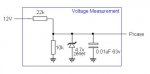
In what way might I interface/buffer 12V (automotive) as digital input
to the Picaxe28X1? I'm supposing the voltage must be dropped to 4-5V?
What components, digital and/or IC should I use? Can anyone point me
to a cicuit?
Suggestions will be appreciated - I need help.
Orville
In what way might I interface/buffer 12V (automotive) as digital input
to the Picaxe28X1? I'm supposing the voltage must be dropped to 4-5V?
What components, digital and/or IC should I use? Can anyone point me
to a cicuit?
Suggestions will be appreciated - I need help.
Orville

")