12V Radiator Fan PWM Control

fritz42_male

Senior Member
Hi all,

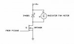
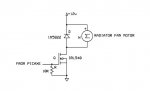
Just a quickie. I need some motor control of a car radiator fan. 12V and approx. 2-3A current. I don't really have any problems with the Picaxe side but can anyone tell me if I would have any issues with the following driver circuit?

I only need to control the speed in one direction. The Picaxe would run off a clean 5V supply with only a common ground.

Thanks
 

Attachments

Janne

Senior Member
Hi,

It's a bit suspicious, it the motor can be driven without a fet driver driving the FET gate.. I'd include a (for example) TC4420 driver in between the picaxe PWM output and the fet gate. Remember to include a pulldown resistor in any case to the picaxe output pin, since the pin will be floating for the first few moments after picaxe is switched on, or when picaxe is not powered.

Also, the diode needs to be able to widhstand the freewheeling current of the motor, so I'd put at least an 40V 3A 1N5822 schottky diode instead of the 4001.
 

MartinM57

Moderator
Or a logic level FET - IRL520 if I remember. May need to start at full power then reduce if you just want to run slowly initially - experiments needed!
 

techElder

Well-known member
I would put a BYPASS switch on there considering how important the radiator fan is to the overall operation of the vehicle.

Consider that the electronics could fail in either the OPEN or CLOSED condition.
 

Dippy

Moderator
Whoa there Big Boy! :)

What sort of PWM frequency are you planning?
Just because you have chosen a Logic Level MOSFET does NOT mean the Gate capacitance has magically disappeared.
READ the device data sheet before getting carried away.
If you are fast PWMing then you will need a driver such as suggested by Janne.

It is common to have a little cap across motor too.
I would also suggest a reasonable 'reservoir' capacitor at the 12V side of the motor too.
A low ESR electro will reduce the transients in the 12V power line supply which will reduce nasties in the system.
 

MPep

Senior Member
It is common to have a little cap across motor too.
Indeed. Also, a (little) cap from motor +ve to motor case, and a cap from motor case to motor -ve is common in an attempt to provide noise suppression.
 

RobertN

Member
Be aware the start up current of a DC motor can be 10 times the running current. When current is first applied the motor is like a low resistance short. Measure the non running resistance of the motor to get an idea what the initial current can be. Once the motor starts rotating back EMF limits the current. Starting a motor can be like a race between the thermo - current capabilities of the FET and the start current requirements of the motor.
Current limiting maybe a good idea not only for startup but also if the motor is stalled or heavily loaded.
 

fritz42_male

Senior Member
Thanks for all the suggestions. As per Janne's advice I have ordered the drivers. I expected to have to put capacitors on there but the Picaxe itself is deriving it's power from a separate supply entirely with just a common ground.

Perhaps it would be better if I explain the project and ask for advice:

It's for a Halloween effect. I have 2 automotive 12V radiator cooling fans in a side by side mounting. The effect I want to achieve is a slowish rotation with a light behind so that people can see the 'chopping' effect of the fan blades (none of my guests are epileptic so no worries there).

I would make sure that the speed control is set at max or even out of circuit at startup so that the initial startup current is less of an issue. Once rotating, the fans do no consume enormous amounts of power - perhaps 1A each so I would then bring the PWM controller in and adjust the rotation speed until I was happy.

Any suggestions?
 

RobertN

Member
Some car radiator fans have 2 speeds with a low value (~1 ohm) high watt resistor in series with the fan for a low speed and no resistor for the high speed. If you don't expect the fan to run near maximum speed, it maybe a good idea to have a series resistor in the circuit at all times to help with the high start current and with control of the fan speed. The problem is, a common size radiator fan may require a resistor in the order of tens of watts for continuous operation. Common lamp bulbs can dissipate more than enough heat and may have some properties you can use for lighting. The lamp should be brightest when power is first applied then fade or go out depending on the lamp and fan speed combination. You would have to experiment with different watt lamps to see if any work.

A FET gate driver may not be needed if the PWM frequency is a few KHz. A 100 or 200 ohm series resistor between the PIC and gate would protect the PIC from high capacitive drive current, slow the FET switching speed, and reduce electrical noise. A slower switching speed would result in more heat in the FET, which may not be an issue at lower frequencies.

I like protected FET's (over current and ESD) for new projects, just to give them a chance if something unexpected happens.

Note that when a DC fan is turned off it becomes a generator until it stops rotating. The reverse bias diode across the fan motor must be able to handle the generated current for what ever time it takes the fan to stop. This is a long time for a diode, so the diode must be selected for its continuous current rating.
 

John West

Senior Member
A great thread for me to monitor. I have an 8+ Amp draw 12V radiator cooling fan (a big one) I'm mounting in my motor-home for living area cooling.

At 8 amps it moves a great deal of air (more than I typically need - and it gets loud) so I'm also looking for a good and rugged PWM drive circuit to dial down its RPM with my 20X2 controller bd. I've got all sorts of parts handy for the job but I don't want to overlook any possible problems. I like things that work and keep on working.
 

GKidd

New member
A great thread for me to monitor. I have an 8+ Amp draw 12V radiator cooling fan (a big one) I'm mounting in my motor-home for living area cooling.

At 8 amps it moves a great deal of air (more than I typically need - and it gets loud) so I'm also looking for a good and rugged PWM drive circuit to dial down its RPM with my 20X2 controller bd. I've got all sorts of parts handy for the job but I don't want to overlook any possible problems. I like things that work and keep on working.
Did you ever get an answer, I know it has been quite a while...😀
 

papaof2

Senior Member
I'm aware this thread is almost a teenager but the cheapest route might be to get one of banggood.com's higher current PWM controllers, remove the potentiometer and drive that input from a PICAXE. Just pick a PWM device that's capable of 50% more current than the fan needs.
 

AllyCat

Senior Member
Hi,

Welcome to the forum. As far as I can see nobody in this thread has used the "Car Radiator Fan" in an actual automobile application, where the environment / requirements of Temperature, Supply Voltage, Reliability and perhaps Safety are far more arduous than for a typical "hobby project".

However, for any application, my starting point would be to first measure the d.c. resistance of the motor with a multimeter and divide it into 15 (volts) to give an absolute minimum design / starting current (i.e. I = V / R). Obviously the FET must be rated to at least this current, but also check from its Data Sheet that the Drain-Source (saturation) voltage is less than (typically) 1 volt for that current, when the Gate-Source Voltage is no more than 4 volts (i.e. a Logic Level FET). Also, if using PWM, begin the design at a Low frequency (probably with a DIV64 in the PICaxe PWM command) and only increase the frequency if/when a benefit can be demonstrated.

One of my first Automobile projects was to simply "monitor" the operation a Radiator Cooling Fan, but even then, there was a "gotcha" because I overlooked that these fans often "Windmill" when not being powered. ;)

Cheers, Alan.
 

neiltechspec

Senior Member
I have used one in an automotive application.

08M2 using 2khz pwm driving two irl540's. Been in use for at least 6 years.
Temp of rad return measured using DS18B20.

edit: current version now on 14M2, needed extra I/O for serial temp display.
 
Last edited:
Top