12v car battery input to picaxe help please.
- Thread starter kando
- Start date
That depends on the picaxe chip i'm going to use.Whats the the supply voltage to the PICAXE ?
I thought about using a 28x2 module for an idea I have and that states a 7-12V input on pin 28 of the module. I could use a separate 5v supply on pin 25 or if i use a different chip.
Hi Dippy,Opps, wrong post.
While I'm here... how did you determine those component values?
And do you understand why srnet asked his question?
I presumed Srnet just wanted to know if it was going to be two different voltages one at 5V and the other at 12V. I'm wondering whether to keep them completely separate perhaps by a relay or opto chip or to link the negatives.
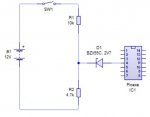
I determined the components by using circuit wizard and found that with the zenor 2.7 it kept the voltage to under about 3volts if the car battery got an increase to 14/15V by the alternator.
The 10k and 4.7k resistor brought the voltage to a max of 4.8 at 15V and 3.8 at 12V. as a voltage divider just before the zenor. If there is a better way I am always open to suggestions from the masters!
I was asking if this was an ok circuit to use. I don't want to blow the picaxe chip.
Does the 28x2 module cope very well at 12volts do you know? Or is there a preferred other method. I presume it has 7805 or something equiv to cope with the voltage.
Regards.
Kando
Last edited:
I'm not sure it's going to do what you think. The 2.7V zener wired as your diagram will try to keep Picaxe pin 4 at 2.7V below the nominal "12V" (maybe 15V) supply. This will be a Bad Thing, applying over 12V to pin 4I was asking if this was an ok circuit to use.
Which 28X2 module? Are you just trying to power the module from 12V, and have an on-off switch?Does the 28x2 module cope very well at 12volts do you know?
Okeydoke, "detect ignition on".
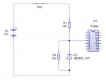
Connect one end of a 10K resistor to the switched twelve volts. Connect the other end to a 4V7 zener +. Connect the zener - end to ground. Connect another 10K resistor across the zener, to provide a pulldown (it also makes a potential divider, but tats okay). Take the Picaxe signal from the junction of both resistors and zener - it will be 4.7V when high, or 0v when low. That's okay for a 5V Picaxe. You'll have to change things for a 3.3V Picaxe.
You could do it cheaper with suitable potential divider only, but a zener is a nice to have safety feature.
Aha, so it's a vehicular system then?
Your voltage divider is Ok but what's that zenEr doing there?
You are simply dropping volts between the divider and PIACXE input.
And at b-all current I don't know what that would be - certainly not your zener voltage.
And maybe when 12V is not switched your input could be vulnereable to noise.
I suspect the reason for srnet asking was that if your PICAXE was powered at fewer volts than your pot/v divider voltage then the I/P would exceed the supply voltage - that's not good.
You should really decide on the PICAXE supply volts before twiddling inputs.
Then you need to look at Manual 2 (or better, a PIC datasheet) to see what the PICaxe of choice considers 'on' (high) and 'off' (low) in terms of volts.
Personally, I would put a small ceramic cap and a zener (Vz depending on PICAXE Vsupply) in parallel with R2.
That takes the edge off any H/F spikes and decouples noise a bit.
Hi Dippy,
Rossko came in with an idea for me. Would you still put a ceramic cap parallel with r3 in the latest circuit or do you think it will be ok for spikes?
I got the idea that the zenner would keep the chip from getting too much voltage but I see now there is a better way. Thanks for the info on manual 2 and i will look at which chip i will use for the up-coming project i have in mind.
Kando
Last edited:
I presumed that there would be two different voltages, by why or how could I assume the PICAXE was at 5V ????I presumed Srnet just wanted to know if it was going to be two different voltages one at 5V and the other at 12V. I'm wondering whether to keep them completely separate perhaps by a relay or opto chip or to link the negatives.
Most of the time I run PICAXEs at 3.0V.
Kando: In this case best you keep in mind classic warnings re wiring PICAXEs into vehicle electrics! At the least this may influence resale value (or your insurance should a claim arise),while at the worst... I'd especially caution re wiring anything at the ignition switch-can't ON/OFF detection be made via existing car devices? Best you detail just what you are intending to eventually do!I'm open to any electronic suggestions as i'm not good in this field and i do get mixed up.
Thought-perhaps consider running off a compact & cheap 12V-5V USB cigarette socket adaptor plug?
Manuka...
Not to get too worried... This project of mine will be for an old digger with a broken ECU. I'm just running it through the thought processes. I now have a sort of wiring diagram.
So no resale problems! and no insurance problems either. It won't go unless i make something to make it go!
Thank you very much for the concern and will keep this forum post for updates.
Regards.
Kando
This seems simple enough.
I hesitate to post, with my limited knowledge. But if I was making this circuit I would use a fuse, first of all.
Secondly, I wouldent rely soly on high wattage resistors. use a diode, and a cap to smooth out the noise thats going to come with the automotive supply.
An option -a 7805 regulator. This will accept voltages up to 35V, your 14.0V supply will be fine. This regulator will help smooth out the supply.
Datasheet below-
https://www.jameco.com/Jameco/Products/ProdDS/876221.pdf
I am sure there are better ideas! Just 2c
Hi, I was looking at the options for this zener arrangement. On a recent project, I found that if the zener current wasn't reached the thing behaved as a normal diode.
Looking at the datasheets for some of these zeners, it seems they need 5mA to 'act' like a zener.
Has anyone else heard of this, or come across this?
regards john
Looking at the datasheets for some of these zeners, it seems they need 5mA to 'act' like a zener.
Has anyone else heard of this, or come across this?
regards john
Hi John,
Firstly, the "forward" characterestic of a "zener diode" is just like a normal silicon diode (i.e. about 650 mV), it is the reverse characteristic which provides the "reference" voltage.
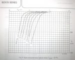
Strictly, "zener action" only occurs at low voltages (less than ~5 volts) and indeed the "knee" is rather soft, so some mA are essential to give a "useful" voltage drop. Higher voltage "zener" diodes actually change to using "avalanche breakdown" (which despite the name is not normally destructive) that has a much sharper knee. Here is a graph of a typical family of zener diodes (which I posted in a thread on this forum some time ago, but the search engine couldn't find it). Note that the curves aren't even plotted below a few mA. Sorry, I didn't scan the higher voltage graphs, but from about 9 volts the knees are sufficiently sharp that currents below 1 mA can be used effectively.
A point of interest is that zener action has a negative temperature coefficient whilst avalanche breakdown has a positive tempco. (often quite large). Thus 5.6 volt "zeners" (which use both) generally have the lowest (nominally zero) tempco.. Also, the base-emitter reverse breakdown of most low power transistors has an excellent knee and can be used as a "reference voltage" at just a few uAs. But the actual voltage is not well specified (typically between 5 and 10 volts) so it has limited use.
Cheers, Alan.
Firstly, the "forward" characterestic of a "zener diode" is just like a normal silicon diode (i.e. about 650 mV), it is the reverse characteristic which provides the "reference" voltage.
Strictly, "zener action" only occurs at low voltages (less than ~5 volts) and indeed the "knee" is rather soft, so some mA are essential to give a "useful" voltage drop. Higher voltage "zener" diodes actually change to using "avalanche breakdown" (which despite the name is not normally destructive) that has a much sharper knee. Here is a graph of a typical family of zener diodes (which I posted in a thread on this forum some time ago, but the search engine couldn't find it). Note that the curves aren't even plotted below a few mA. Sorry, I didn't scan the higher voltage graphs, but from about 9 volts the knees are sufficiently sharp that currents below 1 mA can be used effectively.
A point of interest is that zener action has a negative temperature coefficient whilst avalanche breakdown has a positive tempco. (often quite large). Thus 5.6 volt "zeners" (which use both) generally have the lowest (nominally zero) tempco.. Also, the base-emitter reverse breakdown of most low power transistors has an excellent knee and can be used as a "reference voltage" at just a few uAs. But the actual voltage is not well specified (typically between 5 and 10 volts) so it has limited use.
Cheers, Alan.
Attachments
-
 67.9 KB Views: 16
Alleycay: Hi alan, thanks for the valuable info, its forty years since I learned about zeners, and my memory just gets worse!
I actually came across this problem recently, where the zener current was'nt high enough. It was using a 3.3v zener to protect
the input pins of a raspberry pi. This was fed through a 10k resistor/transistor, and the voltage measured across the diode was around
1.95v...
Thanks again Alan,
regards john
Hi John,
Yes, lower-voltage zeners can have such a "soft" knee that it may be better to use a string of a few forward-biassed diodes (say 0.6 volt each). In fact I think it was the BZY88 family which had a "1V2" version that just had two normal (forward biassed) diodes in series, inside the standard package.
An interesting alternative to low-voltage zeners is to use LEDs. Some Red LEDs drop only just over a volt (at fairly low current), but Yellow and Green nearer to 2 volts and Blue/White around 3 volts, with the added advantage that they emit some light when "catching" an over-voltage.") Of course the exact limiting voltages are not "guaranteed", whilst they are for a zener, but then the curves I posted above don't give too much confidence in what an actual limiting voltage will be (or more particularly, at what voltage they won't upset the normal circuit operation).
Of course the exact limiting voltages are not "guaranteed", whilst they are for a zener, but then the curves I posted above don't give too much confidence in what an actual limiting voltage will be (or more particularly, at what voltage they won't upset the normal circuit operation).
Personally, if I needed to catch (protect) a voltage in the region of +3 volts, I'd probably connect it to the emitter of a PNP transistor, with its base to a divider chain about 0.6 volts lower (and collector to ground). Not totally "bomb proof" but probably better than relying of the "static protection" diodes (to VDD) of a typical microchip.
Cheers, Alan.
Yes, lower-voltage zeners can have such a "soft" knee that it may be better to use a string of a few forward-biassed diodes (say 0.6 volt each). In fact I think it was the BZY88 family which had a "1V2" version that just had two normal (forward biassed) diodes in series, inside the standard package.
An interesting alternative to low-voltage zeners is to use LEDs. Some Red LEDs drop only just over a volt (at fairly low current), but Yellow and Green nearer to 2 volts and Blue/White around 3 volts, with the added advantage that they emit some light when "catching" an over-voltage.
Of course the exact limiting voltages are not "guaranteed", whilst they are for a zener, but then the curves I posted above don't give too much confidence in what an actual limiting voltage will be (or more particularly, at what voltage they won't upset the normal circuit operation).Personally, if I needed to catch (protect) a voltage in the region of +3 volts, I'd probably connect it to the emitter of a PNP transistor, with its base to a divider chain about 0.6 volts lower (and collector to ground). Not totally "bomb proof" but probably better than relying of the "static protection" diodes (to VDD) of a typical microchip.
Cheers, Alan.