Hi,
I've never used the IRIN command in a Project, so was surprised to learn that although the PICaxe IROUT command transmits 12 bits of data, the IRIN command returns only 7 of them. Of course 128 "buttons" is still plenty for a Remote Control system, particularly for any one of 32 "devices" (or channels), but it could useful to be able to transmit at least one full Byte of Data. So the intention here is to receive all 12 bits (in a single word, W1), which can be subdivided, for example, as a Byte with 16 possible "labels", e.g. "Low Byte", "High Byte", "Outdoors/Temperature/Humidity", "Forwards Range", Sideways Range", etc..
The Sony IR Protocol (which IROUT/IRIN employ) is not difficult to decode and well within the capabilities of a PICaxe running at 32 MHz, but I prefer to design even my "fast" Code Snippets to run at 16 MHz. That leaves some "headroom" in case of difficulties later, but it's also the highest clock frequency that is specified to normally drive Servos and the (M2's) "time" variable, etc.. It proved an interesting challenge because the "core decoding loop" can include only about 4 or 5 carefully chosen instructions in sequence, but the final result appears to be reliable and "tolerant".
The "heart" of the code is a (software-implemented) Shift Register which receives one Databit each time it is "clocked". Each time it shifts (e.g. with a *2 or /2 command for M2s), a zero it loaded at the "input" end, which can be used as the default received bit for the "tightest" loop, i.e. the shortest (PWM) bit period. Also, the Register can be pre-loaded with any binary value, which shifts out at the other end (and is then lost), but can be used to mark (or count) when a specific number of shifts have occurred (so a separate counter may be unnecessary). For the Sony/IROUT protocol the shortest bit-period represents a "0", nominally 2 * 567 us (i.e. a 50% duty cycle), which corresponds to 4536 of the "base PIC" Instruction Cycles at 16 MHz. The "1" bit is coded as a double-length pulse (of modulated carrier), with an unchanged "gap" duration, so the nominal period is 3 * 567 us, or 6804 base PIC ICs. This additional period can be used to set the associated data-bit (to a "1") , with some additional time available to output a "Marker" pulse for Demonstration and debugging, etc..
The code is particularly optimised around the IF ... THEN {GOTO} ... branching format which has a characteristic that the jump (GOTO) path takes around 50% longer to execute (1200 ICs = 300 us) than the alternative "fall through" path (800 ICs = 200 us). So, as far as possible, the "tight" core loop uses the fall-through route, but of course one jump ("backwards") is required to close the loop. These branches are sometimes combined in a "list" of identical instructions, which gives the feature of "sampling" the tested condition every 800 ICs (200 us), and also gives the opportunity to fall into an "Over-Run Error" route.
Furthermore, a "number of bits received" counter may be omitted, because the data packet terminates with a "long" gap (i.e. the end of transmission), so the exit/test can be inserted into the "Gap Over-Run Error" path. The program has the option of inserting either PULSOUT or PAUSEUS instructions, which can be used to validate and/or optimise the timing of the code. Unsurprisingly, the execution time of these two instructions is very similar (since both have a timing parameter in tens of microseconds or ICs), but their "overhead" is quite large at about 700 ICs (i.e. a PULSOUT {pin} , 1 executes in 710 ICs), but then the delay increases by 10 ICs for each parametric unit. The data (bits) are received LSB first, so Right-Shifting is preferred, but Left-Shifting is faster and easier to implement with M2 chips. However, in this version, by using a bit-addressable (Word) variable, there is an adequate timing margin to use Right-Shifts.
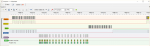
The code has been primarily devised with a 20M2, which is slightly slower than the 08M2, but significantly faster than the X2 family (at the same SETFREQ) that may require changes to (or removal of) the "padding" (Pulse/Pause) instructions. It is configured as a "blocking" subroutine, such that a (potential) data packet must be received before it RETURNs to the main program, but it could be configured as an Interrupt Routine (triggered by the first IR carrier pulse on the input pin) if required. Then a simple Test Harness reports sample values (once each second) to the PE Terminal via a SEROUT. The test input signal was taken from another PICaxe (08M2) using an IROUT command, then the (40 kHz) carrier modulation removed by a simple R-C Low-Pass filter. A time constant of 10k / 2n2 was adequate, but a diode added to enhance the pullup, because the modulation High level has only a 33 % duty cycle (i.e. its average is Vdd / 3). Typical results are shown in the Logic Analyser screenshot.
Cheers, Alan.
I've never used the IRIN command in a Project, so was surprised to learn that although the PICaxe IROUT command transmits 12 bits of data, the IRIN command returns only 7 of them. Of course 128 "buttons" is still plenty for a Remote Control system, particularly for any one of 32 "devices" (or channels), but it could useful to be able to transmit at least one full Byte of Data. So the intention here is to receive all 12 bits (in a single word, W1), which can be subdivided, for example, as a Byte with 16 possible "labels", e.g. "Low Byte", "High Byte", "Outdoors/Temperature/Humidity", "Forwards Range", Sideways Range", etc..
The Sony IR Protocol (which IROUT/IRIN employ) is not difficult to decode and well within the capabilities of a PICaxe running at 32 MHz, but I prefer to design even my "fast" Code Snippets to run at 16 MHz. That leaves some "headroom" in case of difficulties later, but it's also the highest clock frequency that is specified to normally drive Servos and the (M2's) "time" variable, etc.. It proved an interesting challenge because the "core decoding loop" can include only about 4 or 5 carefully chosen instructions in sequence, but the final result appears to be reliable and "tolerant".
The "heart" of the code is a (software-implemented) Shift Register which receives one Databit each time it is "clocked". Each time it shifts (e.g. with a *2 or /2 command for M2s), a zero it loaded at the "input" end, which can be used as the default received bit for the "tightest" loop, i.e. the shortest (PWM) bit period. Also, the Register can be pre-loaded with any binary value, which shifts out at the other end (and is then lost), but can be used to mark (or count) when a specific number of shifts have occurred (so a separate counter may be unnecessary). For the Sony/IROUT protocol the shortest bit-period represents a "0", nominally 2 * 567 us (i.e. a 50% duty cycle), which corresponds to 4536 of the "base PIC" Instruction Cycles at 16 MHz. The "1" bit is coded as a double-length pulse (of modulated carrier), with an unchanged "gap" duration, so the nominal period is 3 * 567 us, or 6804 base PIC ICs. This additional period can be used to set the associated data-bit (to a "1") , with some additional time available to output a "Marker" pulse for Demonstration and debugging, etc..
The code is particularly optimised around the IF ... THEN {GOTO} ... branching format which has a characteristic that the jump (GOTO) path takes around 50% longer to execute (1200 ICs = 300 us) than the alternative "fall through" path (800 ICs = 200 us). So, as far as possible, the "tight" core loop uses the fall-through route, but of course one jump ("backwards") is required to close the loop. These branches are sometimes combined in a "list" of identical instructions, which gives the feature of "sampling" the tested condition every 800 ICs (200 us), and also gives the opportunity to fall into an "Over-Run Error" route.
Furthermore, a "number of bits received" counter may be omitted, because the data packet terminates with a "long" gap (i.e. the end of transmission), so the exit/test can be inserted into the "Gap Over-Run Error" path. The program has the option of inserting either PULSOUT or PAUSEUS instructions, which can be used to validate and/or optimise the timing of the code. Unsurprisingly, the execution time of these two instructions is very similar (since both have a timing parameter in tens of microseconds or ICs), but their "overhead" is quite large at about 700 ICs (i.e. a PULSOUT {pin} , 1 executes in 710 ICs), but then the delay increases by 10 ICs for each parametric unit. The data (bits) are received LSB first, so Right-Shifting is preferred, but Left-Shifting is faster and easier to implement with M2 chips. However, in this version, by using a bit-addressable (Word) variable, there is an adequate timing margin to use Right-Shifts.
The code has been primarily devised with a 20M2, which is slightly slower than the 08M2, but significantly faster than the X2 family (at the same SETFREQ) that may require changes to (or removal of) the "padding" (Pulse/Pause) instructions. It is configured as a "blocking" subroutine, such that a (potential) data packet must be received before it RETURNs to the main program, but it could be configured as an Interrupt Routine (triggered by the first IR carrier pulse on the input pin) if required. Then a simple Test Harness reports sample values (once each second) to the PE Terminal via a SEROUT. The test input signal was taken from another PICaxe (08M2) using an IROUT command, then the (40 kHz) carrier modulation removed by a simple R-C Low-Pass filter. A time constant of 10k / 2n2 was adequate, but a diode added to enhance the pullup, because the modulation High level has only a 33 % duty cycle (i.e. its average is Vdd / 3). Typical results are shown in the Logic Analyser screenshot.
Code:
; (Sony SIRC) IRIN Receiver with 12-bit result, AllyCat March 2021

#picaxe 20m2    ; Other M2s might need some timing modification(s)
#no_data
#terminal 9600      ; Or SERTXD = 19200 at SETFREQ M16
;#define BITS12     ; 12 bit result in w1, Else b2=Data (0-127),b3=Device(1-31)
#define DEMO      ; Diagnostics and Send timing pulses to Marker pin

symbol IDLE = 0              ; Quiescent Input Logic level
symbol sirpin = pinb.7    ; Sony IR Input pin (might want to be interruptable)
symbol echo = c.5           ; Echo data output (IROUT command)
symbol marker = b.3       ; For test/debug only
symbol BAUD = n9600_16   ; A.0 is Prog/SerOut on 20M2

    pause 1000            ; Wait for Terminal to start
    setfreq m16
#IFDEF DEMO
Vdd2dp:     ; Check the supply voltage (Optional Diagnostic)
symbol CALVDD     = 52429     ; 1024*1.024*1000/20  (DAC steps * Ref V / Resolution in mV)
    calibadc10 w1                       ; Measure FVR (nominal 1.024 v) relative to Vdd (1024 steps)
    w2 = w1 / 2 + CALVDD        ; Effectively round up CALVDD by half a (result) bit
    w2 = w2 / w1                         ; Take the reciprocal to calculate (half) Vdd (tens of mV)
    calibadc10 w1                         ; Read the value again because noise may be present :)
    w1 = CALVDD / w1 + w2        ; Calculate Vdd/2 again and add in the first value
    serout a.0,BAUD,("Vdd= ",#w1,"0 mV",cr,lf)
#ENDIF

main:
    low marker
do
    gosub sirin   ; 12-bit (Sony) version of IRIN returned in w1
report:    ; Test Report once per second
#IFDEF DEMO
    if w2 <> time then
        serout a.0,BAUD,(#b3,":",#b2,"=")
        for b1 = 1 to 7
            bit29 = bit16              ; Avoid corrupting the returned data
            serout a.0,BAUD,(#bit16)   ; LSB of w1
            w1 = w1 / 2
        next
        w1 = w1 / 2         ; Shift right
        for b1 = 1 to 5
            serout a.0,BAUD,(#bit16)
            bit29 = bit16       ; Avoid corrupting the data
            w1 = w1 / 2
        next
        serout a.0,BAUD,(cr,lf)
        w2 = time
    endif
    irout echo,b3,b2      ; Echo the data (5 + 7 bits)
#ENDIF
loop

sirin:        ; IR Receiver for Sony (IRIN) protocol (~120 bytes)
    high marker
    if sirpin = IDLE then sirin     ; Wait for carrier pulse to start (if not interrupt)
; Enter/interrupt here when pulse starts: (first pulse is run-in for 2.4ms)
interrupt:
    w1 = $1000                     ; Fill with zero bits and Load End marker (for Right Shift)
    pulsout marker,10           ; For Demo/testing
swait:
    if sirpin = IDLE then swait       ; 800    ; Reject a short pulse
    pause 1                                   ;1300
    if sirpin = IDLE then swait      ; Check pulse every ~500 us
    pulsout marker,30                  ;1000
    if sirpin = IDLE then swait      ; Fall through after ~2 ms
waitsync:
    if sirpin <> IDLE then waitsync    ; Fall through when gap starts (polls every 1200 ICs)
sync:      ;* Start of primary loop *
    if sirpin <> IDLE then framed    ;* 1200    ; Wait for carrier pulse to start (800 polling)
    if sirpin <> IDLE then framed    ;   800    ;* Nominal "0" loop = 4800 (range 4000 - 5600)
    if sirpin <> IDLE then framed    ;   800
    if bit16 = 1 then done12           ; Timeout, but marker has arrived at LSB
    goto longgap                            ; Or try again (but maybe continuous silence)
framed:           ; Jump has taken 1200 so elapsed = 1200-2000
    w1 = w1 / 2                               ;* 1050    ; Shift Right (0 loaded) next test 3050-3850
#IFDEF DEMO
    pulsout marker,10            ;*  800    ; Sampling marker
    if sirpin = IDLE then sync      ;* 1200    ; Jump to wait for next pulse (sync) min loop 4250
    pulsout marker,50             ;+  400    ; "1" bit marker / Delay (fallthrough = 800)
#ELSE
    pauseus 10                         ;*  800    ; Trimming delay (200us)
    if sirpin = IDLE then sync      ;* 1200    ; Jump to wait for next pulse (sync) min loop 4250
    pauseus 50                         ;+  400    ; Additional delay (fallthrough = 800)
#ENDIF
    bit28 = 1                         ;+  400   ; Set Data bit to 1 (alternatively b3=b3 OR 16)
    if sirpin = IDLE then sync         ;+ 1200  ; Wait for pulse to end min "1" loop = 6250
    if sirpin = IDLE then sync         ;   800    ;+ Nominal "1" loop 7200 (6000 - 8400)
    if sirpin = IDLE then sync         ;   800    ; Fall through if pulse too long
longpulse:
    serout a.0,BAUD,("1-")    ;  Perhaps go back to try again (carrier must finish eventually)
    bit31 = 1
longgap:
    serout a.0,BAUD,("Bad")
    bit30 = 1
done12:            ; Marker flag is still in LSB
    low marker       ; For Demo/testing
#IFDEF BITS12
    w1 = w1 / 2       ; Shift out the End Marker (12-bit result)
#ELSE
    b2 = b2 / 2       ; Shift out the End Marker (b2=Data, b3=Device)
#ENDIF
return
Cheers, Alan.
Last edited: