Hello,
If you are interested, I have come across an even more simple style of mppt, however you may class it as a pwm or hybrid between a pwm and mppt.
I used to race model solar cars (10W panel with no energy storage except for the momentum of the vehicle, >30km/h top speed around a 100m slot car style track and most of the cars had maximum power point trackers). There was a weight penalty in the form of extra ballast required to encourage people to learn more about matching motors to panels and gearing as the mppt pretty much formed an automatic gearbox with the motor appearing as a short circuit when stalled and almost open at top speed, with the mppt allowing the panel to always be run at a constant voltage. Other clever designs I have seen to get around the weight penalty by not having an mppt have included a centrifugal switch to mechanically swap two panels from being in parallel for high starting currents and torque to series for high final velocities.
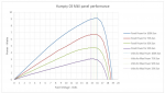
Pretty much all of these "mppts" in these cars were significantly simpler again than Solar Mike's design, although possibly less accurate depending on setup and knowledge of the solar panel they are paired with, measuring only the solar panel voltage and using the rule of thumb that the mppt voltage is 80% of the open circuit voltage - see the graph of power vs voltage for one of my cars' panel.
This allowed m2 chips to be fast enough to respond to short races and quick changes in sun levels, simple and cheap enough for students to build (and modify the firmware as needed). They would operate by turning the motor off on start, measuring the open circuit voltage (assuming the voltage regulator and microcontroller have negligible current draw), then behaving as a buck voltage regulator except trying to regulate the input voltage by varying the duty cycle of the mosfet instead of keeping the output voltage constant. Every so often they might momentarily turn the motor off to get a new open circuit voltage reading as it can change with temperature of the panel.
When stalled, this system could easily be pushing 4 or 5 amps through the moderately small motor in bright sunlight.
In the interests of marginal gains, later designs used the hardware pwm in 14m2s to use a second mosfet as well as the shotkey flyback diode across the (brushed) motor to reduce losses from voltage drop across just the shotkey diode
.
The event's website is here if you want to know a bit more about the cars:
https://www.modelsolar.org.au/
I built a boost version of one of these mppts to charge lead acid batteries from a lower voltage panel, which can be found here:
https://github.com/jgOhYeah/Solar-MPPT-Boost-Lead-Acid-Battery-Charger
A couple of commercial ones designed for the cars can be found here (one is picaxe based and a few are based on comparators and a manual adjust to the correct mppt voltage or atmel microcontrollers):
https://www.scorpiotechnology.com.au/starter-solar-challenge-kits
In the graph, sun levels are percentages of 1000W/m^2, as measured by the event organiser's calibrated light box of halogen globes.
Hope you find this interesting.