Hi,
Welcome to the forum. It depends on the exact rating of the pump/motor but probably not reliably with a single BC337. The pullup resistor is typically 35k but the base PIC data sheet indicates that it could be much higher (IIRC 200k+). Thus the collector current may be limited to 10 mA or less, so I suggest a FET as above, or a pair of BC337s in a Darlington or emitter-follower driver configuration.
Cheers, Alan.
EDIT: The above was composed on my mobile phone so is perhaps mercifully concise for quite a complex issue.
")
To "expand" on the detail, the Microhip data sheet specifies the pullup current to be between 25 and 300 microAmps with a supply of 5 volts and the pin at zero volts (~page 323 of the 08M2 "base PIC" data sheet). Many microcontrollers actually have "(Constant) Current Source" outputs (i,e, the current might be typically 100uA whether the pin is at zero or 4 volts) but the Microchip pullups do appear to be "normal" resistors, so we can calculate their value (from Ohms Law R = V/I). Thus the pullup resistors might be anywhere between 200k and 17k, but in practice they seem to be "nearly always" around 30k - 35k.
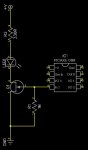
Thus the 1 Mohm pulldown suggested above for a FET is not unreasonable; if only 100k had been chosen then the voltage divider would be 35k : 100k and we would lose over a volt drop to the gate of the FET. Beware that not only is a "logic level" FET required, but their "Threshold Voltage" specifies the highest voltage where the FET may still be "OFF", so several more volts might be needed for it to conduct "well" (i.e. with a low voltage drop at a reasonable current).
For "low" voltages a bipolar transistor may be preferable because its base-emitter voltage is always around 0.6 volt so it will receive most of the available current from the pullup resistor. But bipolar transistors have a finite current gain (collector current divided by base current) of usually around 100, but a value nearer to 20 may be necessary if we want to use it as a "switch" with a low voltage drop. Hence my comment above that the collector current might be limited to 10 mA (i.e. 4v / 40k * 100 = 10 mA).
A "Darlington" configuration uses two similar (NPN or PNP) bipolar transistors with their collectors connected together and one emitter connected to the other's base. Using the remaining emitter and base (and the common collectors) it behaves like a transistor with a high current gain, similar to the product (multiplication) of their gains, i.e. over 1,000. However, it has two restrictions, the base-emitter voltage is doubled (i.e. to about 1.2 volts) and the lowest Vce "saturation" voltage is about 600 mV (because below this, the output transistor "steals" the base current from the first, via its collector diode). These somewhat compromise its behaviour as either a "switch" (emitter grounded) or as an emitter follower (collectors connected to the supply).
 26.9 KB Views: 421
 53.4 KB Views: 296