Are there any Apps to turn an Android smart phone into a Picaxe controller?

wapo54001

Senior Member
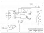
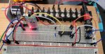
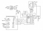
I enjoy doing macro photography. I'm building a focus stacking controller to drive the focus ring of my camera using a geared stepper, stepper driver board, and a Picaxe (probably a 20x2 and an 08m2 to include IR control) to handle the calculations and control the focus ring & shutter. The goal is to automate the process of taking multiple images at slightly different focus points between the nearest and farthest point of an image so that the entire image is in focus when the multiple images are stacked together to create a single entirely-in-focus image.

I would really like to use my smart phone to set the parameters with a USB-to-Serial cable and pads on the touch screen to set start/end points and a few other control requirements -- I think all I need is Up, Down, OK, Menu and Reset buttons, plus a portion of the screen to display text.

I have looked, I think, pretty much everywhere I can think of and find no program/app that provides a user-designable screen layout with USB output of control instructions. The only mention at the Picaxe forum seems to date back to 2010. I guess I could switch to Bluetooth if that was fairly easy to implement, never done that before.

My other alternative may be a Nextion screen.

Is anyone aware of an application that might work on my smart phone?
 

bpowell

Senior Member
I'd think Bluetooth is the way to go.

I'm sure there are appps out there for sending commands via Bluetooth ... I've made a remote control before to turn LEDs on and off .... I recall using a phone app. If I can remember the app name, I'll post it here.
 

kfjl

Member
Hi,
Why do you think you need a 08m2 for IR control? A 20x2 has enough pins to do it all.
What you want to do has already been done with a raspberrypi and a flat-bed scanner, but only for close-up stuff.
You don't need an "app" to be able to control things from a smart phone, just a web page.
I don't understand "USB output of control instructions". The "control instructions" are from the clicks on your web page. You don't need to be connected to a computer.

I haven't done much with Bluetooth. I'm curious to see what @bpowell has up his sleeve. Probably easier than what I have in mind. :)
 

wapo54001

Senior Member
Hi,
Why do you think you need a 08m2 for IR control? A 20x2 has enough pins to do it all.


Because ten years ago I designed the circuit and wrote the code to allow both IR control and a rotary encoder to work simultaneously on a 20X2 with 08M2 support, and a) I'm not good at this and b) haven't done anything with a Picaxe in many many years, and with those handicaps at age 79 I don't want to have to do it again.

What you want to do has already been done with a raspberrypi and a flat-bed scanner, but only for close-up stuff.

I plan to use a Picaxe not an RPI. If I wanted stacking by moving the camera for only small objects, I would use a proper linear rail with a stepper motor not a flatbed scanner. However, this is not just for macro focus stacking but for everything up to sweeping interlaced panoramas. I have already built the camera/motor framework and the toothed gear drive system from the stepper to lens ring; this system is intended to work on any range of focus from a few inches to infinity.

You don't need an "app" to be able to control things from a smart phone, just a web page. I don't understand "USB output of control instructions". The "control instructions" are from the clicks on your web page. You don't need to be connected to a computer.

Interesting, but not enough information for me to understand what you are saying, and I don't think I mentioned the use of a computer. It is intended to be completely self-contained, low-power, lightweight (as much as possible), and portable. All I wanted to know was if anyone knew of a smart phone app that permitted customizing a touch screen and outputting simple ASCII via USB cable.
 

wapo54001

Senior Member
Maybe something like this or this ❓(I've not tried either of them)
Phil, thanks for the suggestions.
The Bluetooth control looked good at first, but I realized that what I have in mind must keep track of steps at all times, plus make some simple calculations of steps between first and last exposure and number of steps between intermediate exposures, etc. The control must have some brains.
 

inglewoodpete

Senior Member
Bluetooth is an option. A few years ago I used Keuwlsoft's Bluetooth Electronics Application on an Android phone to configure my own bluetooth control "app". I see that the latest version of the app allows a USB serial connection to be used, rather than bluetooth.

You configure your "app" in your microcontroller. With the generic Keuwlsoft app loaded and running in your phone, the PICAXE or any mictrocontroller transmits the configuration to the mobile, which then places buttons, dials and gauges on the screen. You can then read values or tap on switch pads to tell you microcontroller what to do.

KeuwlSoft have a range of apps, all with user guides. Well worth any PICAXE enthusiast having a look!
 
Last edited:

wapo54001

Senior Member
Hi,

A nine year old post, but RoboRemo (Free/Demo) still appears to be available, but I have no experience of using it.

Cheers, Alan.
I think it's going to have to be a Picaxe with a two-line OLED display in order to show the steps as I go through a setup sequence before triggering the series of exposures, allowing a primitive menu system etc. When I was wondering about a smartphone I was envisioning two-way communication between the Picaxe and the phone with the phone being the touch screen and data display. All of the very few apps I've looked at are essentially one-way communication. Thanks all for the suggestions, they have helped me understand the underlying requirements more clearly.
 

inglewoodpete

Senior Member
When I was wondering about a smartphone I was envisioning two-way communication between the Picaxe and the phone with the phone being the touch screen and data display. All of the very few apps I've looked at are essentially one-way communication. Thanks all for the suggestions, they have helped me understand the underlying requirements more clearly.
The Keuwlsoft app that I mentioned can send commands by tapping on screen 'touchpads' and receive and display data from the remote microcontroller.
 

wapo54001

Senior Member
Pete, I woke up to your post, and this does look like it will do the job! In fact, the description looks pretty amazing. I will look at it more as soon as I have a moment. Thanks for bringing Keuwlsoft to my attention. It looks pretty amazing, hope it's true. :)
 

Bill.b

Senior Member
I use Bluetooth Electronics Application on my android phone combined with HC-06 receiver for my robot car.
This is part of the code used. Picaxe is a 40x2

Code:
RemoteIn:
REM Controlling car with BT module HC-06 - PICAXE
do
 'b12 = 0  ;clearing memory for commands
 serin [2000],a.0,T9600_16,b12,b13,b14,b15,b16 ;reading from bluetooth (waits 2s for character)
     pause 50
 'debug
 'select b12  ;selection depending on received character
select case b12
 case 65
    gosub FWDFast    'FWD
case 66
    gosub TurnRight    'FWD Right
case 67
    gosub TurnRightR    'REV Right
case 68
    gosub BackFast    'REV
case 69
    gosub TurnLeftR    'Rev Left
case 70
    gosub Turnleft    'FWD Left
case 71
    gosub stopm    'Stop
case 72
    VoiceNo = 33
    GOSUB voice    'camera on
case 73
    VoiceNo = 34
    GOSUB voice        'camera off

case 74
    Pwmduty M1PWM,900
        gosub TurnAround2
case 75
    Pwmduty M1PWM,900    
        gosub TurnAround
 case 113        'Speed
     b17= b14 -48
     if b15 = 10 then
         b18 = 0
          goto loopend
    else
        b18 = b15 -48
     endif
     if b16 = 10 then
         b19 = 0
    else
         b19 = b16 - 48
    endif
end select
loopend:
b7= b17 * 10 + b18 * 10 + b19 'Convert from ASCII to Binary
SpeedCount = b7 * 3 + 200        'Speed count for PWM = 200 to 950
Pwmduty M1PWM,speedCount
loop

return  ;end of loop
Bill
 

PieM

Senior Member
Last edited:

Buzby

Senior Member
I use B4A ( BASIC for Android ) to build apps that connect via Bluetooth. B4A is much like Visual Basic, so I felt at home with it. One of it's great features is that when you open a new project it is pre-populated with the skeleton of a typical app, so getting started is easy. Another goodie is the B4A-Bridge, which lets you use the target device for development. ( There is also an emulator, but that's a bit slow. ) Although B4A is easy to use, it is not a toy. It can be used to develop really compex apps with lots of 'moving parts'.
 

wapo54001

Senior Member
Having looked at the android app and the HC-06 bluetooth module, I think I can do this, using the Picaxe to do the calculations and store the variables, and the smart phone as display and touchscreen control. I think I can use my old 20X2 design and use hserin and hserout connected directly to the HC-06. In my original application the Picaxe could accept a continuous string of commands to do UP and DOWN for volume control using hserin driven by an 08M2 dedicated IR receiver. I hope I can just substitute the HC-06 for the 08M2 in that regard.

I do have some questions starting with this one:

The HC-06 transfers data at 3.3V, but requires 5.0V power.
The Big Easy Driver board has a power pin that can be either 3.3V or 5.0V out, with 85ma load.
The HC-06 requires 40ma, leaving 35ma for the Picaxe circuit.
So, a conundrum -- if I run all the boards at 3.3V from the BED board, I need a separate 5.0V supply for the HC-06. If I run the BED and Picaxe at 5.0V and supply the HC-06 with 5V as it requires, then how do I convert the 3.3V HC-06 output to drive the hserin expecting 5.0V? (I would use a voltage divider to handle the hserout to HC-06 mismatch.) There doesn't seem to be one solution that covers everything without adding another regulator to the mix.
Am I missing something?focus_stacking_5.jpg
 
Last edited:

AllyCat

Senior Member
Hi,
.... how do I convert the 3.3V HC-06 output to drive the hserin expecting 5.0V?
Indeed, the supply rail is not important as such, it is the Logic Level maximum "High Threshold" which is important. The PICs have "Quasi-TTL" inputs where even the maximum High Threshold is less than half of the supply rail, so the inteface would be fine, even allowing for a "noise margin". BUT .....

The HSERIN pin (B.6 = Leg 12) = PIC EUSART RX pin RB5 (PIC18F14K22 Data sheet page 11) is a "ST" (Schmitt Trigger) input which is specified with a maximum High Input threshold of 80% * VDD (parameter D041 page 334) or about 4 volts. :(

However, in practice, I believe the ST inputs have a hysteresis of only a few hundred millivolts and the maximum "Low Level" threshold = VDD * 20% (parameter D037 page 334) is only slightly higher than a TTL input (VDD * 15%), so in reality I think a 3.3v to 5.0 VDD interface will work perfectly well. ;)

IMHO it's rather like the FVR (voltage reference) or the Watchdog (Sleep) Timer which have specified tolerances perhaps ten times worse than their "real world" encountered values. But if you are really worried, you could just add a weak pullup resistor (perhaps 100k) from the RX pin to the 5 volt rail. Many "3.3 volt" I/O pins are either "5 volt tolerant" or have an "electrostatic protection" diode to the supply rail which will limit the voltage to a safe level for the chip (i.e. approximately 4 volts).

Cheers, Alan.
 

AllyCat

Senior Member
Hi,

Maybe that's what the PICaxe data implies, but the 20X2 is a programmed Microchip PIC18F14K22, which on page 11 of the datasheet gives Leg12 (PICaxe B.6, PIC port B.5) as "TTL" (or TLL !) IF it is used as a Logical I/O pin, but it's a "ST" input IF it is used by the EUSART (Hardware) input (which it must be for the HSERIN command to work).

1720694519523.png

Cheers, Alan.
 

kfjl

Member
Whenever I have anything 3.3V tolerant to connect to a picaxe, I run the picaxe off 3.3V. It saves a converter and wiring.
It's always worked for me.
 

wapo54001

Senior Member
Thank you both, it sounds like you agree that it'll work, and that's good enough for me. I'll breadboard it and verify, but it sounds good. The HC-06 apparently is susceptible to damage from a 5V input, so I'll use a voltage divider on hserout and hopefully that's all it'll need. Parts I need arrive today. :p
 

wapo54001

Senior Member
Whenever I have anything 3.3V tolerant to connect to a picaxe, I run the picaxe off 3.3V. It saves a converter and wiring.
It's always worked for me.
That is what I was planning until I found that the HC-06 board requires 5V input to run 3.3V I/O. The BED board makes available up to 85ma of regulated 3.3V OR 5.0V and that is enough power provided I can run the entire circuit off of one voltage or the other. For the cost of two resistors I can avoid providing two voltages with a second regulator circuit (provided the current requirement stays within limits for the BED regulator).
 

AllyCat

Senior Member
Hi,
Whenever I have anything 3.3V tolerant to connect to a picaxe, I run the picaxe off 3.3V. It saves a converter and wiring. It's always worked for me.
Yes, it appears that all the chips above (except the PICaxe) are probably running on 3.3 volts, with the 5 volts just required to give some headroom for the regulators? So my inclination would be to use 3.3 volts also for the PICaxe: BUT.....

The "(optional) Keypad" shows buttons connected directly to 5 volts (?), so you should at least use a series resistor between the keypad and each PICaxe input. Direct connection (to a 3.3v powered PICaxe) would be definitely "dangerous" because it could "phantom power" the PICaxe rail up to about 4.3 volts, or might even destroy its protection diode(s).

More generally, although the PIcaxe has reduced input threshold levels (i.e. "TTL"), many CMOS integrated circuits will use standard CMOS thresholds, where the nominal value is VDD / 2, so the maximum "High" threshold might be higher than 3.3 volts if used with a 5 volt rail (and taking into account noise margins, etc.).

Cheers, Alan.
 

wapo54001

Senior Member
Hi,

The "(optional) Keypad" shows buttons connected directly to 5 volts (?), so you should at least use a series resistor between the keypad and each PICaxe input. Direct connection (to a 3.3v powered PICaxe) would be definitely "dangerous" because it could "phantom power" the PICaxe rail up to about 4.3 volts, or might even destroy its protection diode(s).

Cheers, Alan.
The schematic is a work in progress, the 'optional' display and keyboard were what I intended to do before I found the smart phone app. This new schematic is in line with what I plan now.

I suppose I need to ground all the unused pins. The 20X2 has more pins than I need, but I'm using it because of the background receive capability -- I think I need that to receive successive pulses from the smartphone to move the stepper continuously from one focal point to another when doing the setup.

focus_stacking_51.jpg
 

wapo54001

Senior Member
I am at the first stage of getting this project to work. I have assembled an HC-06 module and a 20X2 using hserin and hserout, and linked a spare smart phone to the Bluetooth module. I wrote a simple routine for the 20X2 to take the hserin input from the BT module and send it back out hserout back to the module, and I have a simple android terminal program installed on the phone to transmit letters to the module.

The good news is that when I send a letter from the phone to the picaxe, it does send a reply back to the phone. The bad news is that I can't get it to reflect back the same thing (an ascii letter) that I sent out. I get back what seems to be a random number instead. I have tried a variety of things changing the details of hsersetup etc, but to no avail. Can anyone look at the attached pics and see what the problem is? I don't think the hardware setup is a problem, it all seems to be working, but I'm stymied.

The two pictures are of the terminal program -- the sent text is in light blue, the reply is in green -- sent out letters, got back numbers.IMG_20240717_155319.jpgIMG_20240717_163617.jpgIMG_20240717_163856.jpg

Here is the simple code I'm using:

Code:
#Picaxe 20X2
#No_Data
#No_Table
SETFREQ m16

HSERSETUP B9600_16,5    'CHANGED B,1 TO B,5 TO INVERT RECEPTION
SYMBOL Cmd_Code = W10

Main:
    DO
    LOOP WHILE ptr = hserptr
    Cmd_Code = @ptrinc
   SERTXD (#W10)
    hserout 0, (#W10)
    ptr = hserptr 'clear queued commands to prevent runon
GOTO Main
 

inglewoodpete

Senior Member
ASCII uses 8-bit data format. While it is possible to use word variables for the transactions, you are creating a lifetime of headaches for yourself. Keep it simple. Try the following code:

Rich (BB code):
#Picaxe 20X2
#No_Data
#No_Table
SETFREQ m16

HSERSETUP B9600_16, %00111 'Binary representation: keep it simple
SYMBOL Cmd_Code = b10

Main:
    DO
    LOOP WHILE ptr = hserptr
    Cmd_Code = @ptrinc
    SERTXD ("(", Cmd_Code, "), ", #Cmd_Code, CR, LF)
    hserout 0, (Cmd_Code)
    ptr = hserptr 'clear queued commands to prevent runon
GOTO Main
 

wapo54001

Senior Member
Pete, this is wonderful, you got me most of the way on the right track -- tried HSERSETUP B9600_16, %00111 and it sent continuous characters and locked up the terminal app BUT changed it to #00001 and it worked perfectly! And found that I could send single letter commands to the Picaxe and have it respond with full prepared sentences back to the terminal which is exactly what I need. Hallelujah.
:D

Using a smartphone app with Bluetooth is an incredible step up. I did a similar project -- IR control of an audio preamp -- using an IR remote and OLED display, and it was a pain. This is in an entirely different universe of easier!
 
Last edited:

wapo54001

Senior Member
It appears that the android app that InglewoodPete mentioned above will allow me to switch from a 20X2 (having the background receive capability) to a 20M2 or 14M2 that can accept one or two characters in the background. Using the Keuwlsoft Android app, pressing a virtual button on the touchscreen sends one code, and then releasing it sends a different code. Thus, you can set a loop in motion with one code and then stop it with the second code which is what I would need to move camera focus from one plane to another plane without pressing a button several thousand times.

My question is the use of the one pin to support SERTXD and HSEROUT. The most germane discussion I found on this goes back to 2015, and suggests you can do both on the one chip as long as you do a chip restart when you try to download new code into the Picaxe. So, do I have it right that you can hardwire both a computer connection with PE6 AND a bluetooth module simultaneously on HSEROUT and run the program with both connected and have them both work OK when required, with the caveat that the picaxe must be restarted whenever a new download is started?

Wondering what happens in the real world with this arrangement. Below is Technical's comment from 2015:

Technical
Technical Support
Staff member


The reason it gets confusing is that the hsersetup command configures the pin to use the special internal EUASRT silicon.
Therefore the EUSART polarity setting can invert the signal and any bit-bashed commands like debug/sertxd etc may then not work correctly as the pin is EUSART controlled, not normal output controlled.

So as along as you *only* use hserout on that pin (don't try and mix with debug etc), and accept that you may need to do a hard-reset for a new download, then you should be ok.
 

AllyCat

Senior Member
Hi,

Do you actually want to output HSEROUT and SERTXD/Programming on the same pin (which I don't think is possible with the 20M2/X2 anyway)? I would have thought that you might need to send different ASCII data to the Bluetooth and Computer channels, but provided that you send only single bytes/characters to the UART first (using either HSEROUT or POKESFR to the Transmit buffer), then the OS can bit-bang the SERTXD (or SEROUT) at much the same time as the UART Hardware is streaming out the bits on a different pin.

On the 08 and 14M2, HSEROUT and SERTXD are indeed allocated to the same pin, but it's possible to move the UART output to a different pin by POKESFRing a bit to the APFCON (Alternate Pin Function Control) register. I believe the register needs to be Poked after the HSERSETUP command and then SERTXD will be output on the default pin as normal.

Cheers, Alan.
 

inglewoodpete

Senior Member
Personally, I would not use a 20M2 over the 20X2. The 20X2 is a far superior chip, with scratchpad and enhanced command set. I don't know what the price differential is but a dollar or two in my currency would not persuade me to change my mind (unless I was buying a significant number of chips).
 

wapo54001

Senior Member
The relative simplicity of the program and the very neat capabilities of the smartphone app make in-program SERTXD unnecessary I think. I just wanted to be sure that I could use HSEROUT and also re-program on the same pin without issues.

Further, it turns out that not only can I do everything with single byte commands from the smartphone, I also only need four connections between the stepper driver board and the Picaxe plus one pin to control a relay, plus the hardware serial pins so the 14M2 is my chip of choice at this point. In addition, the smaller footprint is welcome as well. I'll attache the 14M2 schematic.

Focus Stacker 14M2.jpg
 

inglewoodpete

Senior Member
(Post #29)
"The reason it gets confusing is that the hsersetup command configures the pin to use the special internal EUASRT silicon.
Therefore the EUSART polarity setting can invert the signal and any bit-bashed commands like debug/sertxd etc may then not work correctly as the pin is EUSART controlled, not normal output controlled.

So as along as you *only* use hserout on that pin (don't try and mix with debug etc), and accept that you may need to do a hard-reset for a new download, then you should be ok.
"
The EUSART vs bit-bang clash goes a little further than being a problem when using both methods on a single pin. (I'm presuming that the last sentence in the quote above is your comment on what Technical said in 2015.)

Bit-banged commands like SerTxd, SerIn and SerOut rely on each command having total control of the chip while in progress. To do this, these commands have to disable all background interrupts like Timers or the EUSART.

The hSerIn and hSerOut commands rely on background interrupts to work correctly. Eg the EUSART generates a background interrupt when its 1-byte receive register is full or its transmit register is empty. If a string of data is being sent or, particularly, received in the background while a bit-banged command on any pin is in progress, there is a high risk that characters will get missed. Similarly, Timer ticks might be ignored too.
 

wapo54001

Senior Member
Making progress, have modules moving the stepper forward and back and stopping appropriately. Now working on sending text and data messages back from the Picaxe to the smartphone screen, and there's something I can't figure out -- how to use HSEROUT to send a Word-sized number to the screen as text.

I get it that the value must be sent a byte at a time and I've tried to make it work but I just don't get anywhere. What I am trying to do is to send a Word value -- say, W5=24,351 -- as text to the smartphone screen.

The manual says this below, but I don't understand how to translate that into sending the text value of the number in W5. Help, please?!

main:
for b0 = 0 to 63 ; start a loop
read b0,b1 ; read value into b1
hserout 0,(b1) ; transmit value to serial LCD
next b0 ; next loop
 

Aries

New Member
Look at the bintoascii function (if you don't want to handle it yourself).
Something like (untested)
Code:
w5 = 24351
bintoascii w5,b0,b1,b2,b3,b4
hserout 0,(b0,b1,b2,b3,b4)
 

AllyCat

Senior Member
Hi,

AFAIK it does only work (directly) with bytes, so if you specify a word it will only send the low 8 bits ! But the # converts a byte (or word) to individual ASCII digits, as does BINTOASCII. To send a word completely in/as two bytes it appears that you need to know that for example w5 = b10 (low byte) + b11 (high byte), so you would use HSEROUT 0 , (b10 , b11).

For PEEK, POKE and READ, etc. you can use the WORD qualifier (e.g. READ pointer , WORD w5 is converted to READ pointer , b10 , b11) , but it appears not for SER... commands. Thus it appears that you can't use S_Wx in a {H}SEROUT command, but I would use them with caution anyway because I recall finding a "bug" it their use. I don't recall the exact details, but I believe that it "forgot" to clear it's High byte when reading a byte from (e.g.) EPROM.

Personally, I rarely use BINTOASCII because it's so greedy in memory, both program and variables (which I believe you think you're running out of). But if you do need to use it, you could try bptr = 30 : BINTOASCII w5 , @bptrinc , @bptrinc , @bptrinc , @bptrinc , @bptr and then much the same for the {H}SEROUT.

Note that HSERIN and HSEROUT work quite differently between M2 and X2 chips, because the M2s don't use interrupts (as much), but I'm not sure if or why you still need to use the H... versions. Sorry, I could add much more detail but I am currently "traveling".

Cheers, Alan.
 

wapo54001

Senior Member
Hi,

AFAIK it does only work (directly) with bytes, so if you specify a word it will only send the low 8 bits

Cheers, Alan.
Well, I tried this to try it out and it worked!

Code:
Set_LensNearLimit:
stepperposition_val = 34560
HSEROUT 0, ("Focus Minimum Permissible set OK ", #stepperposition_val)
GOTO Main
 

AllyCat

Senior Member
Hi,

So it sent Five ASCII bytes "34560" (I.e. decimal 51,52,53,54,48)? Is that what you want the app to receive ?

I can only use the simulator at the moment, but strangely, using a word variable (without the # to convert it to ASCII bytes) appears to send nothing. :( But it does send a byte variable (as indicated by the command reference).

Cheers, Alan.
 
Last edited:
Top