Rampz
Well-known member
Hello All
I thought it best to start a new thread for this, just testing a tilt switch has run to 6 pages.
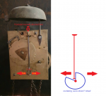
The goal is to regulate the time of a clock by increasing or decreasing the pendulem swing by elctromagnet against the actual time, seems the best to use a DS3231 as PhilHornby says a very accurate time chip, first goal to buy one and get the time and date up on a screen, with the ability to provide a level of correction as required
Later to get a reliable pick up from the clock as to where it thinks the time is and look at how to regulate it, i do know a bit about how its done with current versions and can apply similar lines in this project, have some ideas to then take the project further than anyone currently does
I thought it best to start a new thread for this, just testing a tilt switch has run to 6 pages.
The goal is to regulate the time of a clock by increasing or decreasing the pendulem swing by elctromagnet against the actual time, seems the best to use a DS3231 as PhilHornby says a very accurate time chip, first goal to buy one and get the time and date up on a screen, with the ability to provide a level of correction as required
Later to get a reliable pick up from the clock as to where it thinks the time is and look at how to regulate it, i do know a bit about how its done with current versions and can apply similar lines in this project, have some ideas to then take the project further than anyone currently does