5V Source for SN754410 "ENABLE" Pins

4jaba6

New Member
I am using this chip for a motor control project.

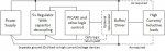
Pins 1 and 9 need to be enabled with +5V on this chip for the motors to run.

+ 5v source goes to a 10K Resistor and then splits to the 2 pins.

In past, have used a Separate +5V source ( or used +5V from VCC1 CHIP Logic Power (pin 16 ).

I am asking for opinions on which of the two +5v source to use.
I believe the approved solution is the VCC1.
Am trying to determine the pros & cons.
It seems that using a separate +5V source's only downside is extra parts and extra space.
What are con's of using VCC! ?

TIA,

John
 

inglewoodpete

Senior Member
Some people had experienced problems using the SN754410, as discussed here. I've only ever used the larger L298, which was used because I was driving larger motors, so can't comment personally on the SN754410.

When driving a motor off the same supply as the microcontroller, ensure that each has it's own power wiring all the way back to the power source (Ie no motor current shares a wire with the microcontroller).

Logic Earth2.jpg
 

westaust55

Moderator
There is no problem in using the +5 V d.c. powering the SN754410 Vcc1 to also pull the two enable pins high - using a 10 kOhm pull up resistor as you suggest.

Remember also to ensure that the 0 Volt line to the SN754410 is also connected to the 0 Volt line for the microcontroller.

like IWP I have never used the SN754410 myself - always the L293D in the past (recently have been using a DMOS H-bridge driver with much lower internal volt drop - but only available as a SMS package).
 

inglewoodpete

Senior Member
Remember also to ensure that the 0 Volt line to the SN754410 is also connected to the 0 Volt line for the microcontroller.
As tempting as it might be to connect the two device 0v points directly, the 0v line between should be routed via the power source. That will all but eliminate current surges and back-EMF from the reactive load affecting the relative voltage on the 0v pin of the PIC.
 

4jaba6

New Member
There is no problem in using the +5 V d.c. powering the SN754410 Vcc1 to also pull the two enable pins high - using a 10 kOhm pull up resistor as you suggest.

Remember also to ensure that the 0 Volt line to the SN754410 is also connected to the 0 Volt line for the microcontroller.

like IWP I have never used the SN754410 myself - always the L293D in the past (recently have been using a DMOS H-bridge driver with much lower internal volt drop - but only available as a SMS package).

westtaust55,

Thanks to you and Inglewoodpete for your replys.
By "0 volt line", I believe you are referring to ground ( 4 pins on SN754410 ).
Please correct me if wrong assumption.

I have used this chip in past with success controlling small motors.
The motors were driven by 5v.
If using larger motors, I would use the L298.


John
 

westaust55

Moderator
By "0 volt line", I believe you are referring to ground ( 4 pins on SN754410 ).
Please correct me if wrong assumption.
Yes, 0 volt is what is often referred to as “ground”.
But if battery powered or through many power supplied The 0 volt connection is not connected to ground (and thus is not earthed/grounded as is the metalwork on a mains powered device).
 

4jaba6

New Member
As tempting as it might be to connect the two device 0v points directly, the 0v line between should be routed via the power source. That will all but eliminate current surges and back-EMF from the reactive load affecting the relative voltage on the 0v pin of the PIC.
Hi Peter,

Regarding your schematic Sept. 13, 2020:
I do not understand your comment on Sept. 14, 2020: "0v line should be routed via the power source".

It has always been my understanding that 0v from microcontroller and SN754410 were supposed to be tied together!?!?
i.e the 4 grounds on the SN... go to a SN...ground rail and one lead from this rail goes to the microcontroller ground rail.
I understand the change in your diagram will prevent or nearly eliminate the fly back EMF
This apparently would help solve some of the "flakey" motor responses.

I am planning on using your schematic but have two connection questions.

It looks like the 0v (ground) from the power source splits and one lead goes to v. regulator and continues on to the microcontroller ground rail.
The second lead goes to ground on the high current/voltage devices ( SN754410 and motors ).

Q1. First question: The second lead goes to buffer and on to high current inductive loads ( is that the 0v pins 4, 5,12,13 on the SN754410 ? ).

I am using a separate +5v to power the 2 motors that would go to pin 8 vcc2 on the SN754410.

Q2 . A second question: Where does the 0V from the separate motor supply tie in? I believe it is the 2nd ground lead to high current devices and pins 4,5,12,13 on SN754410 . ( ? )

If I have this wrong, can you please post (hopefully easy to construct ) a SPECIFIC schematic of the 0v and +5v lines for the microcontroller, SN754410, and the two power source ( +5v for microcontroller/SN754410 including pin 16, ground pins and separate +5v motor supply including pin 8 on SN754410 ) ?

Thanks in advance,

Best to You,

John
 

inglewoodpete

Senior Member
Hi Peter,

Regarding your schematic Sept. 13, 2020:
I do not understand your comment on Sept. 14, 2020: "0v line should be routed via the power source".
From what you've written below, I think you understand the principles. Each "group" of components should have their ground (0v) wires run back to their power source in a "star" fashion. You should avoid the temptation to "daisy chain" the 0v lines together. You need to avoid having heavy, electrically noisy motor current from sharing a wire that the microcontroller uses. If the motor and microcontroller share a ground wire, noise on the wire can cause the voltage on microcontroller's ground pin to shift sufficiently to disturb it's operation.
It has always been my understanding that 0v from microcontroller and SN754410 were supposed to be tied together!?!?
i.e the 4 grounds on the SN... go to a SN...ground rail and one lead from this rail goes to the microcontroller ground rail.
I understand the change in your diagram will prevent or nearly eliminate the fly back EMF
This apparently would help solve some of the "flakey" motor responses.

I am planning on using your schematic but have two connection questions.

It looks like the 0v (ground) from the power source splits and one lead goes to v. regulator and continues on to the microcontroller ground rail.
The second lead goes to ground on the high current/voltage devices ( SN754410 and motors ).

Q1. First question: The second lead goes to buffer and on to high current inductive loads ( is that the 0v pins 4, 5,12,13 on the SN754410 ? ).

I am using a separate +5v to power the 2 motors that would go to pin 8 vcc2 on the SN754410.
The "Buffer" in your case is the SN754410. Yes, pins 4, 5, 12, 13 would be commoned together and have one, heavier wire go to its own power supply 0v. A second wire would link the two power supply 0v points - this will link all 0v points together.
Q2 . A second question: Where does the 0V from the separate motor supply tie in? I believe it is the 2nd ground lead to high current devices and pins 4,5,12,13 on SN754410 . ( ? )
This is where we'll need more information. The SN754410 is a Quadruple Half-H Driver and can be used to drive up to 4 motors, depending on their requirements. With a motor connected between one 'Y' output Pin 3, 6, 11 or 14 and ground, it will run in only one direction. If the motor is connected between two 'Y' outputs Eg Pins 3 and 6, the SN754410 can operate as an H-Bridge, allowing the motor to be driven in either direction. Finally, the SN754410 can have all four outputs drive a stepper motor.
If I have this wrong, can you please post (hopefully easy to construct ) a SPECIFIC schematic of the 0v and +5v lines for the microcontroller, SN754410, and the two power source ( +5v for microcontroller/SN754410 including pin 16, ground pins and separate +5v motor supply including pin 8 on SN754410 ) ?

Thanks in advance,

Best to You,

John
 

4jaba6

New Member
From what you've written below, I think you understand the principles. Each "group" of components should have their ground (0v) wires run back to their power source in a "star" fashion. You should avoid the temptation to "daisy chain" the 0v lines together. You need to avoid having heavy, electrically noisy motor current from sharing a wire that the microcontroller uses. If the motor and microcontroller share a ground wire, noise on the wire can cause the voltage on microcontroller's ground pin to shift sufficiently to disturb it's operation.

The "Buffer" in your case is the SN754410. Yes, pins 4, 5, 12, 13 would be commoned together and have one, heavier wire go to its own power supply 0v. A second wire would link the two power supply 0v points - this will link all 0v points together.

This is where we'll need more information. The SN754410 is a Quadruple Half-H Driver and can be used to drive up to 4 motors, depending on their requirements. With a motor connected between one 'Y' output Pin 3, 6, 11 or 14 and ground, it will run in only one direction. If the motor is connected between two 'Y' outputs Eg Pins 3 and 6, the SN754410 can operate as an H-Bridge, allowing the motor to be driven in either direction. Finally, the SN754410 can have all four outputs drive a stepper motor.
Thank you inglewoodpete.

I shall rewire my circuit as per your instructions.
Am also considering using 293D or 298 ( although my motors are only 5v ).
Also westaust55 on Sept. 14,2020 posted the L293D only comes in SMS ( surface mount? )package and I need one that works on a protoboard.

JB
 

AllyCat

Senior Member
Hi,

A problem with many of those H-Bridge driver chips is that they use Bipolar technology (typically Darlington NPNs at top and bottom) so can "lose" 1.5 or 2 volts of drive. That's not an issue if you're using a 20 or 30 volt supply rail, but it might be if you have only a 5 volt supply. What supply voltage are you planning to use and how much current do your motors require (both in "normal" running and when starting/stalled)?

I don't think that westaust55 was saying that the L293D is available only in SMD (Surface Mounting) format, but the "much better" MOS devices that he is now using are available only in SMD format. Note that some of the "well-known" H-Bridge chips are not even specified to operate with a rail as low as 5 volts.

Cheers, Alan.
 

4jaba6

New Member
Hi,

A problem with many of those H-Bridge driver chips is that they use Bipolar technology (typically Darlington NPNs at top and bottom) so can "lose" 1.5 or 2 volts of drive. That's not an issue if you're using a 20 or 30 volt supply rail, but it might be if you have only a 5 volt supply. What supply voltage are you planning to use and how much current do your motors require (both in "normal" running and when starting/stalled)?

I don't think that westaust55 was saying that the L293D is available only in SMD (Surface Mounting) format, but the "much better" MOS devices that he is now using are available only in SMD format. Note that some of the "well-known" H-Bridge chips are not even specified to operate with a rail as low as 5 volts.

Cheers, Alan.

Allycat,

Thanks for your input.
Am using a 5v supply.
Unfortunately the motors are enclosed in plastic and were purchased several years ago as part of a robot kit platform.
I do not have the current data.
I suspect that my SN754410 voltage drops are a result of not using "fly-back" diodes and hence back EMF issues.

At this time, it appears 3 choices:
1. Rewire SN754410 as per inglewoodpete's schematic.
2. L293D ( with the diodes internal ).
Your msg. has alerted me that this option is more possible since this chip can work on a protoboard.
Do you have a specific suggestion for a 293D chip? It would be greatly appreciated.
3. L298, but possibly overkill do to this chip probably for much higher voltages.

Thank you,

John
 

AllyCat

Senior Member
Hi John,

Do you have a multi-meter to measure the running current, and/or a simple d.c resistance measurement can be used to calculate the stall current (which is typically 5 - 10 times higher than the normal running current)? But it sounds as if the motors are not particularly large?
I suspect that my SN754410 voltage drops are a result of not using "fly-back" diodes and hence back EMF issues.
No, the flyback diodes are essential to prevent any of the semiconductors being destroyed by over-voltage spikes from the inductance of the motor. But these diodes may be contained with the H-Bridge package anyway. The forward voltage drops are inherent in the design of devices like the 293, as indicated in its data sheet. For example, the High output voltage will be typically 1.5 volts lower than the supply rail (e.g. "Vcc - 1.4 volts"), and the Low output level about 1 volt above Earth (e.g. "1.2 volts"). Thus the motor might not run at much more than half-speed if you use a bipolar-based bridge, instead of more modern MOS technology. Perhaps a low-cost "breakout" module using one of the SMD packages can be found, but it's not my area of expertise.

Another possible solution could be to use a relay (2 poles changeover) to reverse the motor direction, combined with a low-side FET switch that could also give PWM variable-speed control. Even a Darlington bipolar transistor should drop less than half the voltage of a full bridge. The voltage drop across relay contacts should be negligible, and quite a small relay might be sufficient because a PICaxe controller could switch off the current flow via the transistor before flipping the relay, avoiding any risk of "burning" the relay contacts.

Cheers, Alan.
 

inglewoodpete

Senior Member
(AllyCat...)
2. L293D ( with the diodes internal ).
Your msg. has alerted me that this option is more possible since this chip can work on a protoboard.
Do you have a specific suggestion for a 293D chip? It would be greatly appreciated.
The PICAXE interfacing documentation includes a page on using the L293D. From within PE6, click on "File", "Help" then "Manual 3 - Interfacing Circuits" Refer to page 13.
 

4jaba6

New Member
Hi John,

Do you have a multi-meter to measure the running current, and/or a simple d.c resistance measurement can be used to calculate the stall current (which is typically 5 - 10 times higher than the normal running current)? But it sounds as if the motors are not particularly large?

No, the flyback diodes are essential to prevent any of the semiconductors being destroyed by over-voltage spikes from the inductance of the motor. But these diodes may be contained with the H-Bridge package anyway. The forward voltage drops are inherent in the design of devices like the 293, as indicated in its data sheet. For example, the High output voltage will be typically 1.5 volts lower than the supply rail (e.g. "Vcc - 1.4 volts"), and the Low output level about 1 volt above Earth (e.g. "1.2 volts"). Thus the motor might not run at much more than half-speed if you use a bipolar-based bridge, instead of more modern MOS technology. Perhaps a low-cost "breakout" module using one of the SMD packages can be found, but it's not my area of expertise.

Another possible solution could be to use a relay (2 poles changeover) to reverse the motor direction, combined with a low-side FET switch that could also give PWM variable-speed control. Even a Darlington bipolar transistor should drop less than half the voltage of a full bridge. The voltage drop across relay contacts should be negligible, and quite a small relay might be sufficient because a PICaxe controller could switch off the current flow via the transistor before flipping the relay, avoiding any risk of "burning" the relay contacts.

Cheers, Alan.
Thanks Alan!

I shall consider your suggestions and see if they help with the motor issues.

John
 

4jaba6

New Member
The PICAXE interfacing documentation includes a page on using the L293D. From within PE6, click on "File", "Help" then "Manual 3 - Interfacing Circuits" Refer to page 13.
Peter,

Thank you for the documentation reference.
I also appreciate your schematic dated Sept. 13, 2020 and followup regarding questions I had about specifically relating to SN754410.

Best,

John
 
Top