Hairy Animal
Member
Firstly, apologies if there is already an answer to this query somewhere in this wonderful set of forums, but if there is I haven't been able to find it.
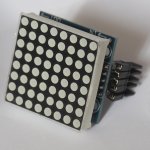
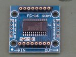
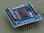
What I'm trying to do is display a message of about 18 characters on four 8x8 LED matrix displays (i.e. 32x8 pixels) using pixel by pixel (column by column) scrolling. The hardware I'm using is (four off of) the FC-16 board & display shown in the attached pictures, which is available from a well known internet auction site for less than 89p (yes really!) per board complete with soldered MAX7219 and the LED matrix display (price when bought as three sets of four boards).
I really want to stick with this hardware because it's easy to understand and simple to drive from any PICAXE chip including the 08M2+ which is what I'm currently using for testing (and cheap). Later, I want to scale up the display to maybe 50 or 60 cms in height (using discrete LEDs) if I can get it working on the small matrix displays first.
This short bit of video shows the sort of effect I'm after but just with a simple chevron pattern:
But displaying a message such as this:
by scrolling one pixel/column at a time is taxing my programming skills somewhat. The code I used for this display draws heavily on westaust55's excellent piece: https://picaxeforum.co.uk/threads/getting-started-with-the-max7219-eight-digit-7-segment-led-driver.23293/ which helped greatly in getting something working very quickly. I would though point out that there are a couple of minor errors in the 08M2 code in this article: "SYMBOL DIn_7219 = pinC.3" - pin 3 is an input only, and "DIRSB = %11100000", should be DIRSC?
My code for the text display is:
The codes in EEPROM have been constructed from the character definitions shown in the code (commented out) by manipulating them in Excel to read the row-by-row values needed to write to the display. The display can only be written to one row (of 32 pixels) at a time, which makes scrolling column by column quite challenging.
I think that the way to do it is to recreate the whole message as an array (of approximately 96 x 8 bits) in RAM, then copy eight 32 x 1 horizontal chunks of it to the display, moving the area to copy one pixel right each time the eight rows have been copied. See the diagram attached. I think this is the approach taken by this Arduino example: https://howtomechatronics.com/tutorials/arduino/8x8-led-matrix-max7219-tutorial-scrolling-text-android-control-via-bluetooth/ , but so far as I can see it only uses two display matrices (16 x 8) which simplifies things a bit.
Looking at the Arduino code I can get the gist of what's being done but code such as " while (*s != 0) { " leaves me a bit nonplussed - it's been 40 years since I did any 'C' coding and very little of it even then. So if anyone could maybe give me a bit of help with this please I'd be most grateful? If it helps, I only want to scroll a fixed message (similar in length to the test message) and not do variable messages on-the-fly as in the Arduino example. Sorry it's rather a long request.
What I'm trying to do is display a message of about 18 characters on four 8x8 LED matrix displays (i.e. 32x8 pixels) using pixel by pixel (column by column) scrolling. The hardware I'm using is (four off of) the FC-16 board & display shown in the attached pictures, which is available from a well known internet auction site for less than 89p (yes really!) per board complete with soldered MAX7219 and the LED matrix display (price when bought as three sets of four boards).
I really want to stick with this hardware because it's easy to understand and simple to drive from any PICAXE chip including the 08M2+ which is what I'm currently using for testing (and cheap). Later, I want to scale up the display to maybe 50 or 60 cms in height (using discrete LEDs) if I can get it working on the small matrix displays first.
This short bit of video shows the sort of effect I'm after but just with a simple chevron pattern:
But displaying a message such as this:
My code for the text display is:
Code:
#PICAXE 08M2
 SETFREQ M32
; Code to write "This is a test screen."
; to a 4-digit matrix display (8x8 LEDs)
; in three screens.
;
; SYMBOL Definitions
;
; Control signal lines from PICAXE to MAX7219
SYMBOL Load_7219  = C.1
SYMBOL Clk_7219   = C.2
SYMBOL DIn_7219   = pinC.4
;
; MAX7219 Registers - these are the rows in the 8x8 matrix.
; Row0 is the top row and Row7 is the bottom.
;
SYMBOL No_Op    = 0
SYMBOL Row0       = 1
SYMBOL Row1       = 2
SYMBOL Row2       = 3
SYMBOL Row3       = 4
SYMBOL Row4       = 5
SYMBOL Row5       = 6
SYMBOL Row6       = 7
SYMBOL Row7       = 8
;
SYMBOL Decode     = 9
SYMBOL Intens     = 10
SYMBOL ScanLim    = 11
SYMBOL ShutDwn    = 12
SYMBOL DigTest    = 15
;
; MAX7219 Data Constants
SYMBOL Set_Off    = 0
SYMBOL Set_On     = 1
SYMBOL No_Digits  = 7   ; Scan limit for rows (all 8).
SYMBOL Dec_Digits = 0   ; turn off decoding of digits for 7-segment display.
SYMBOL Init_Inten = 1   ; 0 (=1/32 PWM on time) to 15 (=31/32 PWM on time).
;
; Define variables
;
SYMBOL Data_7219  = b0
SYMBOL Register   = b1
SYMBOL Character  = b2
SYMBOL RowCount   = b3
SYMBOL Counter    = b4
SYMBOL Latch      = b5
;
; EEPROM character definitions would ideally be used to generate
; the required bit patterns but it's rather complicated.
;
;EEPROM (" " ,3 ,%00000000 ,%00000000 ,%00000000)
;EEPROM ("T" ,5 ,%10000000 ,%10000000 ,%11111110 ,%10000000 ,%10000000)
;EEPROM ("a" ,4 ,%00000100 ,%00101010 ,%00101010 ,%00011110)
;EEPROM ("e" ,4 ,%00011100 ,%00101010 ,%00101010 ,%00011000)
;EEPROM ("h" ,4 ,%11111110 ,%00100000 ,%00100000 ,%00011110)
;EEPROM ("i" ,3 ,%00100010 ,%10111110 ,%00000010)
;EEPROM ("c" ,4 ,%00011100 ,%00100010 ,%00100010 ,%00010100)
;EEPROM ("n" ,4 ,%00111110 ,%00100000 ,%00100000 ,%00011110)
;EEPROM ("r" ,4 ,%00111110 ,%00010000 ,%00100000 ,%00100000)
;EEPROM ("t" ,3 ,%00100000 ,%11111100 ,%00100010)
;EEPROM ("s" ,4 ,%00010010 ,%00101010 ,%00101010 ,%00100100)
;
; These EEPROM definitions define a row at a time for the whole display.
; Screen #1
EEPROM ($7D , $04 , $00 , $80) ; Row 0, top
EEPROM ($11 , $00 , $00 , $00)
EEPROM ($11 , $CC , $71 , $8E)
EEPROM ($11 , $24 , $80 , $90)
EEPROM ($11 , $24 , $60 , $8C)
EEPROM ($11 , $24 , $10 , $82)
EEPROM ($11 , $2E , $E1 , $DC)
EEPROM ($00 , $00 , $00 , $00) ; Row 7, bottom
; Screen #2
EEPROM ($00 , $08 , $00 , $20) ; Row 0, top
EEPROM ($00 , $08 , $00 , $20)
EEPROM ($06 , $1C , $C7 , $70)
EEPROM ($01 , $09 , $28 , $20)
EEPROM ($07 , $09 , $E6 , $20)
EEPROM ($09 , $09 , $01 , $20)
EEPROM ($07 , $04 , $CE , $10)
EEPROM ($00 , $00 , $00 , $00) ; Row 7, bottom
; Screen #3
EEPROM ($00 , $00 , $00 , $00) ; Row 0, top
EEPROM ($00 , $00 , $00 , $00)
EEPROM ($73 , $2C , $C6 , $70)
EEPROM ($84 , $B1 , $29 , $48)
EEPROM ($64 , $21 , $EF , $48)
EEPROM ($14 , $A1 , $08 , $4B)
EEPROM ($E3 , $20 , $C6 , $4B)
EEPROM ($00 , $00 , $00 , $00) ; Row 7, bottom
;
;===============================================
; Initialise the PICAXE Pins for communication with the MAX7219
;===============================================
Init:
    ; DIRSB = %11100000 wrong for an 08M2?
    DIRSC = %00010110
    LOW Load_7219
    LOW Clk_7219
    DIn_7219 = 0
    PAUSE 1000
    GOSUB Initialise7219
;
;===============================================
; Main Program loop
;===============================================
Main:
    PAUSE 5000
    GOSUB Screen1
    PAUSE 10000
    GOSUB Screen2
    PAUSE 10000
    GOSUB Screen3
    PAUSE 10000
    ;GOSUB OverwriteB
    GOTO main
END
;
;===============================================
; Subroutines
;===============================================
; Subroutine to initialise the MAX7219 7-Seg LED display driver
Initialise7219:
FOR Character = 1 TO 4
    Register = Decode  : Data_7219 = Dec_Digits : GOSUB ShiftTo7219
NEXT Character
    PULSOUT C.1, 1 ' minimum high duration is 50 ns -still okay at 64 MHz
FOR Character = 1 TO 4
    Register = Intens  : Data_7219 = Init_Inten : GOSUB ShiftTo7219
NEXT Character
    PULSOUT C.1, 1 ' minimum high duration is 50 ns -still okay at 64 MHz
FOR Character = 1 TO 4
    Register = ScanLim : Data_7219 = No_Digits  : GOSUB ShiftTo7219
NEXT Character
    PULSOUT C.1, 1 ' minimum high duration is 50 ns -still okay at 64 MHz
FOR Character = 1 TO 4
    Register = ShutDwn : Data_7219 = Set_On    : GOSUB ShiftTo7219
NEXT Character
    PULSOUT C.1, 1 ' minimum high duration is 50 ns -still okay at 64 MHz
FOR Character = 1 TO 4
    Register = DigTest : Data_7219 = Set_Off     : GOSUB ShiftTo7219
NEXT Character
    PULSOUT C.1, 1 ' minimum high duration is 50 ns -still okay at 64 MHz
RETURN
;
; Subroutine to shift the register address and data
; values out to one of the four cascaded MAX7219s.
ShiftTo7219:
    PULSOUT Clk_7219, 1 ; bit 15 is don't care
    PULSOUT Clk_7219, 1 ; bit 14 is don't care
    PULSOUT Clk_7219, 1 ; bit 13 is don't care
    PULSOUT Clk_7219, 1 ; bit 12 is don't care
    DIn_7219 = bit11 : PULSOUT Clk_7219, 1
    DIn_7219 = bit10 : PULSOUT Clk_7219, 1
    DIn_7219 = bit9 : PULSOUT Clk_7219, 1
    DIn_7219 = bit8 : PULSOUT Clk_7219, 1
    DIn_7219 = bit7 : PULSOUT Clk_7219, 1
    DIn_7219 = bit6 : PULSOUT Clk_7219, 1
    DIn_7219 = bit5 : PULSOUT Clk_7219, 1
    DIn_7219 = bit4 : PULSOUT Clk_7219, 1
    DIn_7219 = bit3 : PULSOUT Clk_7219, 1
    DIn_7219 = bit2 : PULSOUT Clk_7219, 1
    DIn_7219 = bit1 : PULSOUT Clk_7219, 1
    DIn_7219 = bit0 : PULSOUT Clk_7219, 1
    PAUSE 200   ; Deliberate reduction of write speed
            ; so that the writing can be seen.
            ; Without this it's almost instantaneous.
;
; PULSOUT C.1, 1 ; Latches the data into the MAX7219s.
;
; The above is moved to the main routine so that all 4 devices are
; latched simultaneously with the 4 bytes of serial data.
    RETURN
;
; New versions of the display routine.
Screen1:
    FOR Counter = 0 TO 31
        READ Counter , Data_7219
        Register = Counter / 4
        Register = Register + 1 : GOSUB ShiftTo7219
        Latch = Counter // 4
        IF Latch = 3 THEN : PULSOUT C.1, 1 : ENDIF
        ; Latch the data into all four devices simultaneously.
    NEXT
RETURN
;
Screen2:
    FOR Counter = 32 TO 63
        READ Counter , Data_7219
        Register = Counter - 32
        Register = Register / 4
        Register = Register + 1 : GOSUB ShiftTo7219
        Latch = Counter // 4
        IF Latch = 3 THEN : PULSOUT C.1, 1 : ENDIF
    NEXT
RETURN
;
Screen3:
    FOR Counter = 64 TO 95
        READ Counter , Data_7219
        Register = Counter - 64
        Register = Register / 4
        Register = Register + 1 : GOSUB ShiftTo7219
        Latch = Counter // 4
        IF Latch = 3 THEN : PULSOUT C.1, 1 : ENDIF
    NEXT
RETURN
;I think that the way to do it is to recreate the whole message as an array (of approximately 96 x 8 bits) in RAM, then copy eight 32 x 1 horizontal chunks of it to the display, moving the area to copy one pixel right each time the eight rows have been copied. See the diagram attached. I think this is the approach taken by this Arduino example: https://howtomechatronics.com/tutorials/arduino/8x8-led-matrix-max7219-tutorial-scrolling-text-android-control-via-bluetooth/ , but so far as I can see it only uses two display matrices (16 x 8) which simplifies things a bit.
Looking at the Arduino code I can get the gist of what's being done but code such as " while (*s != 0) { " leaves me a bit nonplussed - it's been 40 years since I did any 'C' coding and very little of it even then. So if anyone could maybe give me a bit of help with this please I'd be most grateful? If it helps, I only want to scroll a fixed message (similar in length to the test message) and not do variable messages on-the-fly as in the Arduino example. Sorry it's rather a long request.
Attachments
-
 282.9 KB Views: 4
 -
 235.8 KB Views: 5
 -
 246.9 KB Views: 5
 -
 16 KB Views: 4
")